Paul Boddie's Free Software-related blog


Archive for the ‘PIC32’ Category

Pessimistic perspectives on technological sustainability

Tuesday, August 16th, 2022

I was recently perusing the Retro Computing Forum when I stumbled across a mention of Collapse OS. If your anxiety levels have not already been maxed out during the last few years of climate breakdown, psychological warfare, pandemic, and actual warmongering, accompanied by supply chain breakdowns, initially in technology and exacerbated by overconsumption and spivcoin, now also in commodities and exacerbated by many of those other factors (particularly the warmongering), then perhaps focusing on societal and civilisational collapse isn’t going to improve your mood or your outlook. Unusually, then, after my last, rather negative post on such topics, may I be the one to introduce some constructive input and perhaps even some slight optimism?

If I understand the motivations behind Collapse OS correctly, it is meant to provide a modest computing environment that can work on well-understood, commonplace, easily repaired and readily sourced hardware, with the software providing the environment itself being maintainable on the target hardware, as opposed to being cross-built on more powerful hardware and then deployed to simpler, less capable hardware. The envisaged scenario for its adoption is a world where powerful new hardware is no longer produced or readily available and where people must scavenge and “make do” with the hardware already produced. Although civilisation may have brought about its own collapse, the consolation is that so much hardware will have been strewn across the planet for a variety of purposes that even after semiconductor fabrication and sophisticated manufacturing have ceased, there will remain a bounty of hardware usable for people’s computational needs (whatever they may be).

I am not one to try and predict the future, and I don’t really want to imagine it as being along the same lines as the plot for one of Kevin Costner’s less successful movies, either, but I feel that Collapse OS and its peers, in considering various dystopian scenarios and strategies to mitigate their impacts, may actually offer more than just a hopefully sufficient kind of preparedness for a depressing future. In that future, without super-fast Internet, dopamine-fired social media, lifelike gaming, and streaming video services with huge catalogues of content available on demand, everyone has to accept that far less technology will be available to them: they get no choice in the matter. Investigating how they might manage is at the very least an interesting thought experiment. But we would be foolish to consider such matters as purely part of a possible future and not instructive in other ways.

An Overlap of Interests

As readers of my previous articles will be aware, I have something of an interest in older computers, open source hardware, and sustainable computing. Older computers lend themselves to analysis and enhancement even by individuals with modest capabilities and tools because they employ technologies that may have been regarded as “miniaturised” when they were new, but they were still amenable to manual assembly and repair. Similarly, open source hardware has grown to a broad phenomenon because the means to make computing systems and accessories has now become more accessible to individuals, as opposed to being the preserve of large and well-resourced businesses. Where these activities experience challenges, it is typically in the areas that have not yet become quite as democratised, such as semiconductor fabrication at the large-scale integration level, along with the development and manufacture of more advanced technology, such as components and devices that would be competitive with off-the-shelf commercial products.

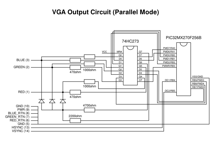
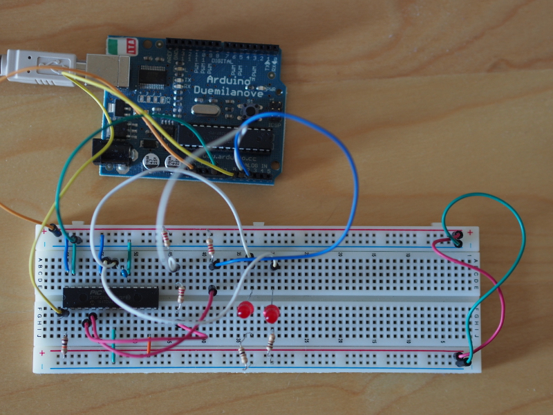
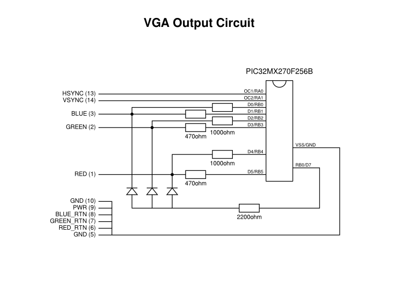
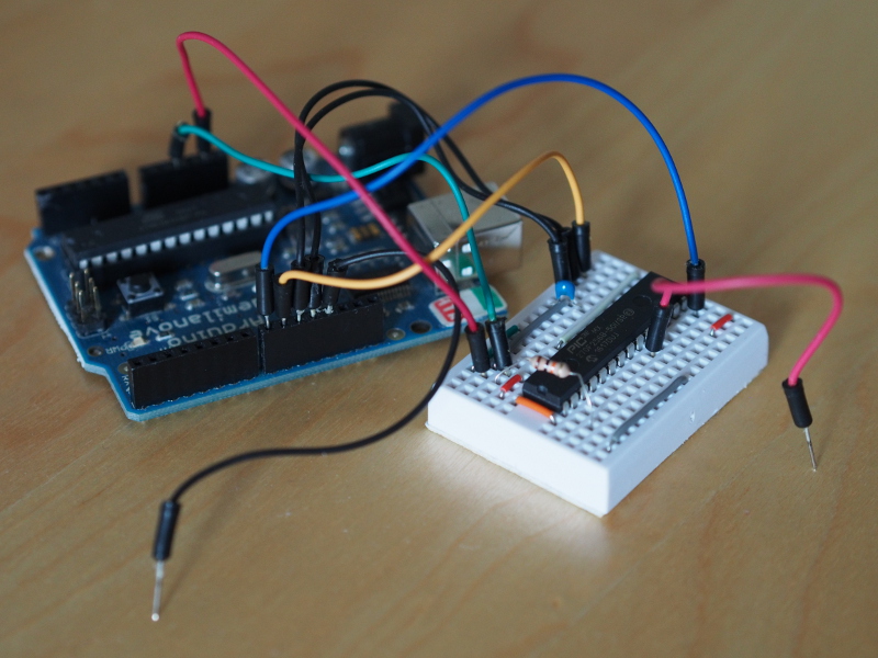
Some of the angst around open source hardware concerns the lack of investment it receives from those who would benefit from it, but much of that investment would largely be concerned with establishing an ability to maintain some kind of parity with modern, proprietary hardware. Ignoring such performance-led requirements and focusing on simpler hardware projects, as many people already do, brings us a lot closer to retrocomputing and a lot closer to the constrained hardware scenario envisaged by Collapse OS. My own experiments with PIC32-based microcontrollers are not too far removed from this, and it would not be inconceivable to run a simple environment in the 64K of RAM and 256K of flash memory of the PIC32MX270, this being much more generous than many microcomputers and games consoles of the 1980s.

Although I relied on cross-compilation to build the programs that would run on the minimal hardware of the PIC32 microcontroller, Collapse OS emphasises self-hosting: that it is possible to build the software within the running software itself. After all, how sustainable would a frugal computing environment be if it needed a much more powerful development system to fix and improve it? For Collapse OS, such self-hosting is enabled by the use of the Forth programming language, as explained by the rationale for switching to Forth from a system implemented in assembly language. Such use of Forth is not particularly unusual: its frugal demands were prized in the microcomputer era and earlier, with its creator Charles Moore describing the characteristics of a computer designed to run Forth as needing around 8K of RAM and 8K of ROM, this providing a complete interactive system.

(If you are interested in self-hosting and bootstrapping, one place to start might be the bootstrapping wiki.)

For a short while, Forth was perhaps even thought to be the hot new thing in some circles within computing. One fairly famous example was the Jupiter Ace microcomputer, developed by former Sinclair Research designers, offering a machine that followed on fairly closely from Sinclair’s rudimentary ZX81. But in a high-minded way one might have expected from the Sinclair stable and the Cambridge scene, it offered Forth as its built-in language in response to all the other microcomputers offering “unstructured” BASIC dialects. Worthy as such goals might have been, the introduction of a machine with outdated hardware specifications condemned it in its target market as a home computer, with it offering primitive black-and-white display output against competitors offering multi-colour graphics, and offering limited amounts of memory as competitors launched with far more fitted as standard. Interestingly, the Z80 processor at the heart of the Ace was the primary target of Collapse OS, and one might wonder if the latter might actually be portable to the former, which would be an interesting project if any hardware collector wants to give it a try!

Other Forth-based computers were delivered such as the Canon Cat: an unusual “information appliance” that might have formed the basis of Apple’s Macintosh had that project not been diverted towards following up on the Apple Lisa. Dedicated Forth processors were even delivered, as anticipated already by Moore back in 1980, reminiscent of the Lisp machine era. However, one hardware-related legacy of Forth is that of the Open Firmware standard where a Forth environment provides an interactive command-line interface to a system’s bootloader. Collapse OS fits in pretty well with that kind of application of Forth. Curiously, someone did contact me when I first wrote about my PIC32 experiments, this person maintaining their own microcontroller Forth implementation, and in the context of this article I have re-established contact because I never managed to properly follow up on the matter.

Changing the Context

According to a broad interpretation of the Collapse OS hardware criteria, the PIC32MX270 would actually not be a bad choice. Like the AVR microcontrollers and the microprocessors of the 1980s, PIC32MX microcontrollers are available in convenient dual in-line packages, but unlike those older microprocessors they also offer the 32-bit MIPS architecture that is nicer to program than the awkward instruction sets of the likes of the Z80 and 6502, no matter how much nostalgia colours people’s preferences. However, instead of focusing on hardware suitability in a resource-constrained future, I want to consider the messages of simplicity and sustainability that underpin the Collapse OS initiative and might be relevant to the way we practise computing today.

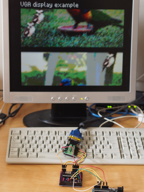
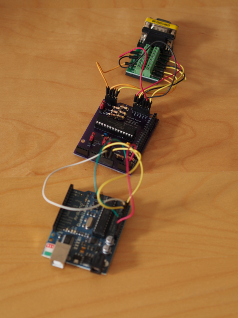
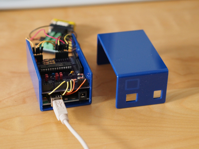
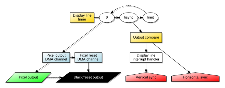
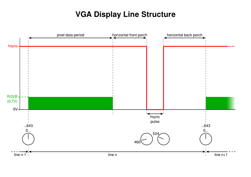
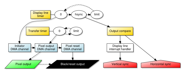
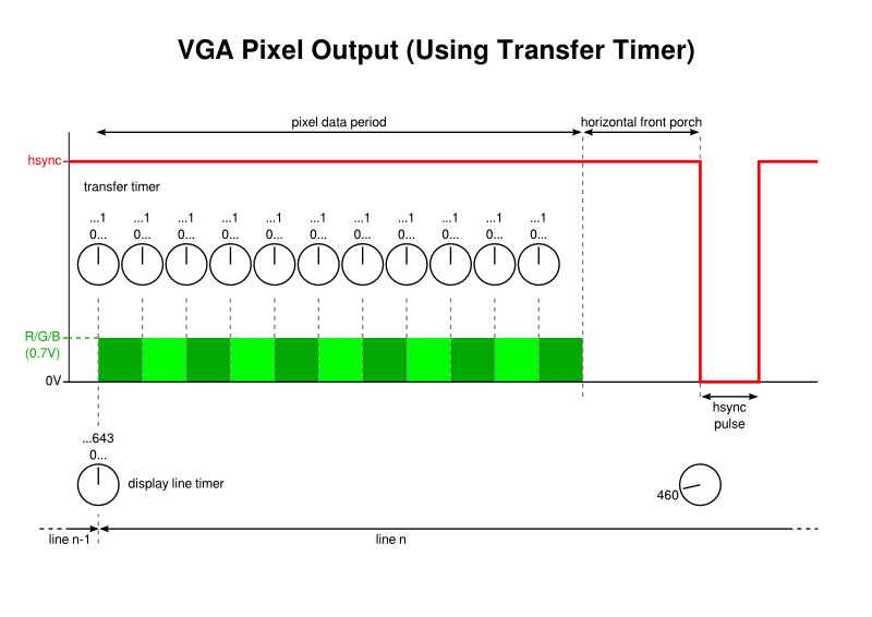
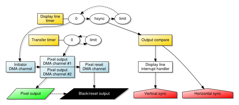
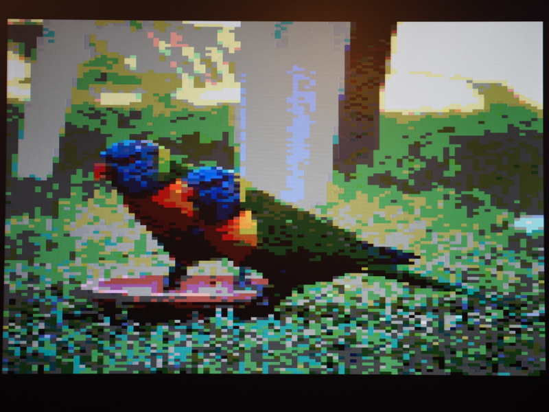
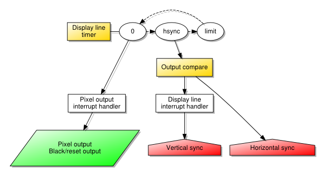
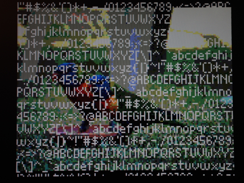
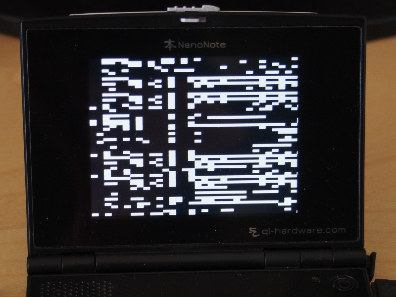
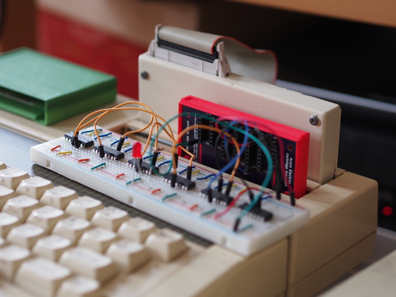
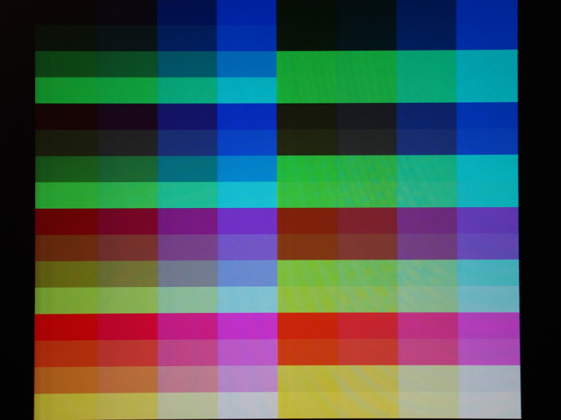
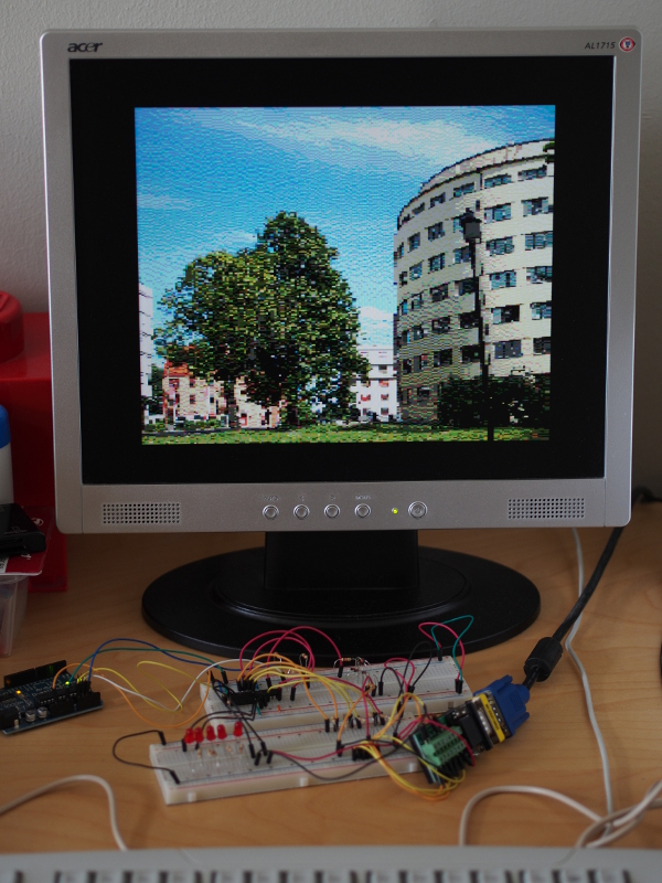
When getting a PIC32 microcontroller to produce a video signal, part of the motivation was just to see how straightforward it might be to make a simple “single chip” microcomputer. Like many microcomputers back in the 1980s, it became tempting to consider how it might be used to deliver graphical demonstrations and games, but I also wondered what kind of role such a system might have in today’s world. Similar projects, including the first versions of the Maximite have emphasised such things as well, along with interfacing and educational applications (such as learning BASIC). Indeed, many low-end microcontroller-based computers attempt to recreate and to emphasise the sparse interfaces of 1980s microcomputers as a distraction-free experience for learning and teaching.

Eliminating distractions is a worthy goal, whether those distractions are things that we can conveniently seek out when our attention wanders, such as all our favourite, readily accessible Internet content, or whether they come in the form of the notifications that plague “modern” user interfaces. Another is simply reducing the level of consumption involved in our computational activities: civilisational collapse would certainly impose severe limits on that kind of consumption, but it would seem foolish to acknowledge that and then continue on the same path of ever-increasing consumption that also increasingly fails to deliver significant improvements in the user experience. When desktop applications, mobile “apps”, and Web sites frequently offer sluggish and yet overly-simplistic interfaces that are more infuriating than anything else, it might be wise to audit our progress and reconsider how we do certain things.

Human nature has us constantly exploring the boundaries of what is possible with technology, but some things which captivate people at any given point on the journey of technological progress may turn out to be distracting diversions from the route ultimately taken. In my trawl of microcomputing history over the last couple of years, I was reminded of an absurd but illustrative example of how certain technological exercises seem to become the all-consuming focus of several developers, almost being developed for the sake of it, before the fad in question flames out and everybody moves on. That example concerned “morphing” software, inspired by visual effects from movies such as Terminator 2, but operating on a simpler, less convincing level.

Suddenly, such effects were all over the television and for a few months in late 1993, everyone was supposedly interested in making the likeness of one famous person slowly change into the likeness of another, never mind that it really required a good library of images, this being somewhat before widespread digital imaging and widespread image availability. Fast-forward a few years, and it all seemed like a crazy mass delusion best never spoken of again. We might want to review our own time’s obsessions with performative animations and effects, along with the peculiarities of touch-based interfaces, the assumption of pervasive and fast connectivity, and how these drive hardware consumption and obsolescence.

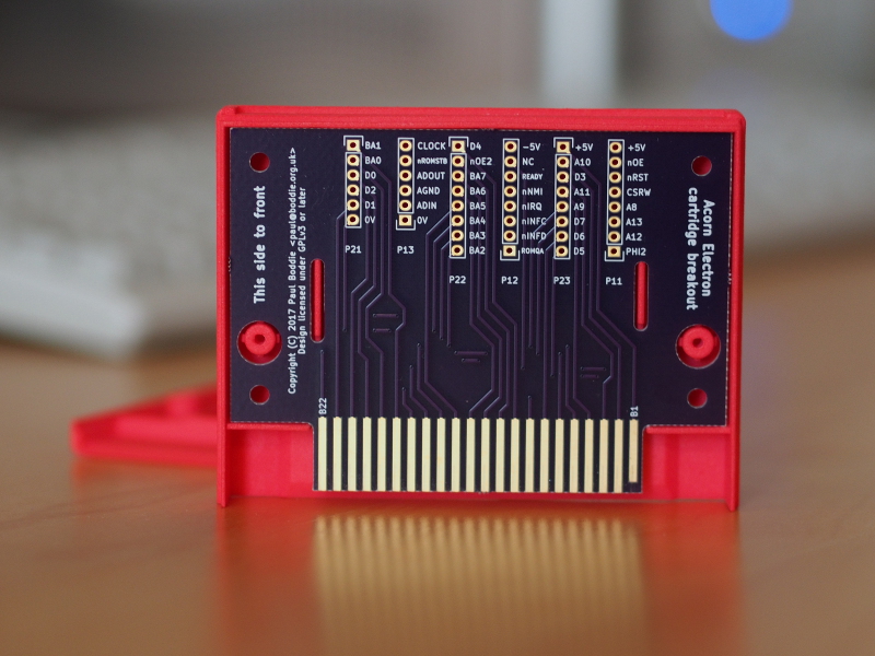
Once again, some of this comes back to asking how people managed to do things in earlier times and why things sometimes seem so complicated now. Thinking back to the 1980s era of microcomputing, my favourite 8-bit computer of those times was the Acorn Electron, this being the one I had back then, and it was certainly possible to equip it to do word processing to a certain level. Acorn even pitched an expanded version as a messaging terminal for British Telecom, although I personally think that they could have made more of such opportunities, especially given the machine’s 80-column text capabilities being made available at such a low price. The user experience would not exactly be appealing by today’s standards, but then nor would that of Collapse OS, either.

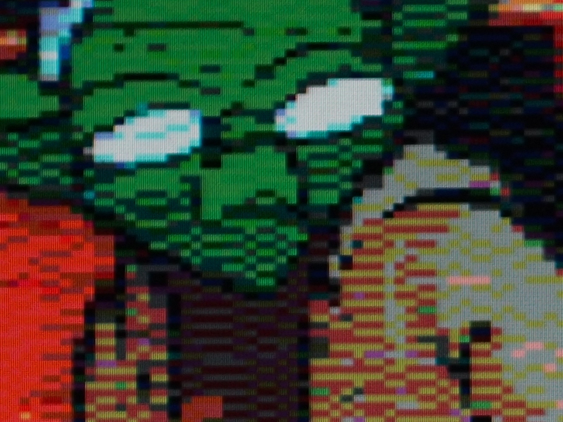
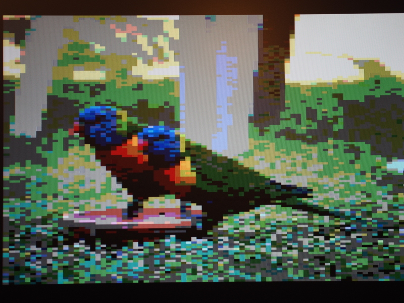
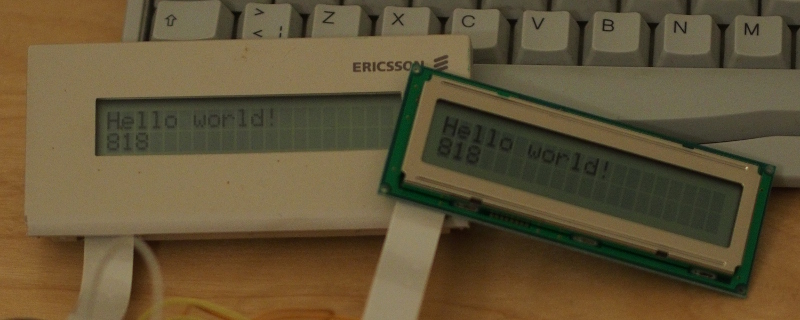
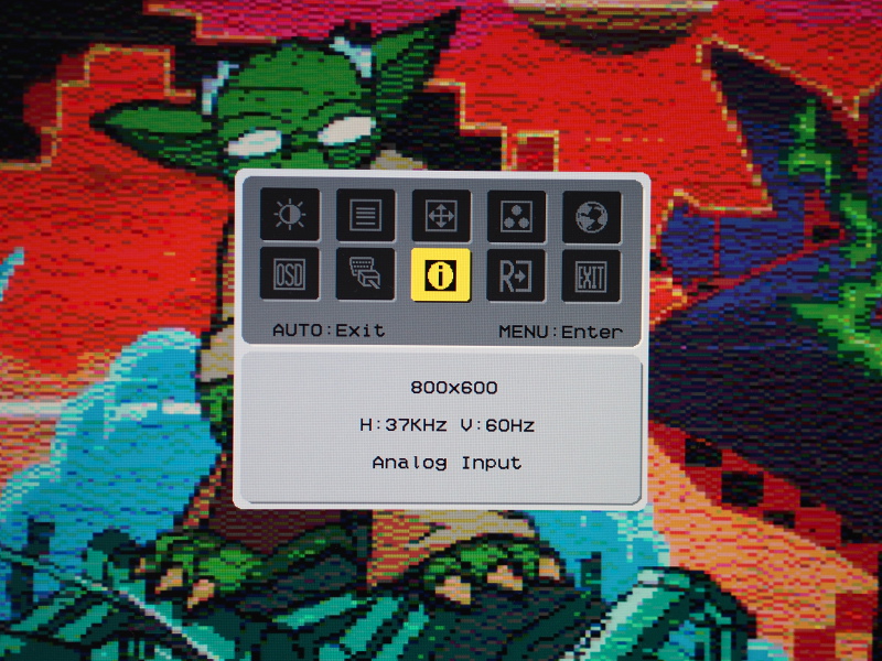
When I got my PIC32 experiment working reasonably, I asked myself if it would be sufficient for tasks like simple messaging and writing articles like this. The answer, assuming that I would enhance that effort to use a USB keyboard and external storage, is probably the same as whether anyone might use a Maximite for such applications: it might not be as comfortable as on a modern system but it would be possible in some way. Given the tricks I used, certain things would actually be regressions from the Electron, such as the display resolution. Conversely, the performance of a 48MHz MIPS-based processor is obviously going to be superior to a 2MHz 6502, even when having to generate the video signal, thus allowing for some potential in other areas.

Reversing Technological Escalation

Using low-specification hardware for various applications today, considering even the PIC32 as low-spec and ignoring the microcomputers of the past, would also need us to pare back the demands that such applications have managed to accumulate over the years. As more powerful, higher-performance hardware has become available, software, specifications and standards have opportunistically grown to take advantage of that extra power, leaving many people bewildered by the result: their new computer being just as slow as their old one, for example.

Standards can be particularly vulnerable where entrenched interests drive hardware consumption whilst seeking to minimise the level of adaptation their own organisations will need to undertake in order to deliver solutions based on such standards. A severely constrained computing device may not have the capacity or performance to handle all the quirks of a “full fat” standard, but it might handle an essential core of that standard, ignoring all the edge cases and special treatment for certain companies’ products. Just as important, the developers of an implementation handling a standard also may not have the capacity or tenacity for a “full fat” standard, but they may do a reasonable job handling one that cuts out all the corporate cruft.

And beyond the technology needed to perform some kind of transaction as part of an activity, we might reconsider what is necessary to actually perform that activity. Here, we may consider the more blatant case of the average “modern” Web site or endpoint, where an activity may end up escalating and involving the performance of a number of transactions, many of which superfluous and, in the case of the pervasive cult of analytics, exploitative. What once may have been a simple Web form is often now an “experience” where the browser connects to dozens of sites, where all the scripts poll the client computer into oblivion, and where the functionality somehow doesn’t manage to work, anyway (as I recently experienced on one airline’s Web site).

Technologists and their employers may drive consumption, but so do their customers. Public institutions, utilities and other companies may lazily rely on easily procured products and services, these insisting (for “security” or “the best experience”) that only the latest devices or devices from named vendors may be used to gain access. Here, the opposite of standardisation occurs, where adherence to brand names dictates the provision of service, compounded by the upgrade treadmill familiar from desktop computing, bringing back memories of Microsoft and Intel ostensibly colluding to get people to replace their computer as often as possible.

A Broader Brush

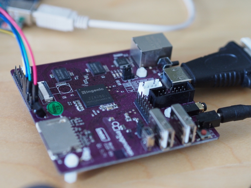
We don’t need to go back to retrocomputing levels of technology to benefit from re-evaluating the prevalent technological habits of our era. I have previously discussed single-board computers like the MIPS Creator CI20 which, in comparison to contemporary boards from the Raspberry Pi series, was fairly competitive in terms of specification and performance (having twice the RAM of the Raspberry Pi Models A+, B and B+). Although hardly offering conventional desktop performance upon its introduction, the CI20 would have made a reasonable workstation in certain respects in earlier times: its 1GHz CPU and 1GB of RAM should certainly be plenty for many applications even now.

Sadly, starting up and using the main two desktop environments on the CI20 is an exercise in patience, and I recommend trying something like the MATE desktop environment just for something responsive. Using a Web browser like Firefox is a trial, and extensive site blocking is needed just to prevent the browser wanting to download things from all over the place, as it tries to do its bit in shoring up Google’s business model. My father was asking me the other day why a ten-year-old computer might be slow on a “modern” Web site but still perfectly adequate for watching video. I would love to hear the Firefox and Chrome developers, along with the “architects of the modern Web”, give any explanation for this that doesn’t sound like they are members of some kind of self-realisation cult.

If we can envisage a microcomputer, either a vintage one or a modern microcontroller-based one, performing useful computing activities, then we can most certainly envisage machines of ten or so years ago, even ones behind the performance curve, doing so as well. And by realising that, we might understand that we might even have the power to slow down the engineered obsolescence of computing hardware, bring usable hardware back into use, and since not everyone on the planet can afford the latest and greatest, we might even put usable hardware into the hands of more people who might benefit from it.

Naturally, this perspective is rather broader than one that only considers a future of hardship and scarcity, but hardship and scarcity are part of the present, just as they have always been part of the past. Applying many of the same concerns and countermeasures to today’s situation, albeit in less extreme forms, means that we have the power to mitigate today’s situation and, if we are optimistic, perhaps steer it away from becoming the extreme situation that the Collapse OS initiative seeks to prepare for.

Concrete Steps

I have, in the past, been accused of complaining about injustices too generally for my complaints to be taken seriously, never mind such injustices being blatant and increasingly obvious in our modern societies and expressed through the many crises of our times. So how might we seek to mitigate widespread hardware obsolescence and technology-driven overconsumption? Some suggestions in a concise list for those looking for actionable things:

  • Develop, popularise and mandate lightweight formats, protocols and standards
  • Encourage interoperability and tolerance for multiple user interfaces, clients and devices
  • Insist on an unlimited “right to repair” for computing devices including the software
  • Encourage long-term thinking in software and systems development

And now for some elucidation…

Mandatory Accessible Standards

This suggestion has already been described above, but where it would gain its power is in the idea of mandating that public institutions and businesses would be obliged to support lightweight formats, protocols and standards, and not simply as an implementation detail for their chosen “app”, like a REST endpoint might be, but actually as a formal mechanism providing service to those who would interact with those institutions. This would make the use of a broad range of different devices viable, and in the case of special-purpose devices for certain kinds of users, particularly those who would otherwise be handed a smartphone and told to “get with it”, it would offer a humane way of accessing services that is currently denied to them.

For simple dialogue-based interactions, existing formats such as JSON might even be sufficient as they are. I am reminded of a paper I read when putting together my degree thesis back in the 1990s, where the idea was that people would be able to run programs safely in their mail reader, with one example being that of submitting forms.

T-shirt ordering dialogues shown by Safe-Tcl

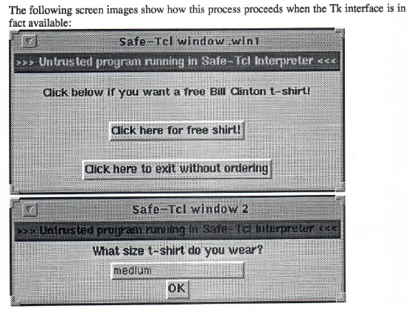
T-shirt ordering dialogues shown by Safe-Tcl running in a mail program, offering the recipient the chance to order some merchandise that might not be as popular now.

In that paper, most of the emphasis was on the safety of the execution environment as opposed to the way in which the transaction was to be encoded, but it is not implausible that one might have encoded the details of the transaction – the T-shirt size (with the recipient’s physical address presumably already being known to the sender) – in a serialised form of the programming language concerned (Safe-Tcl) as opposed to just dumping some unstructured text in the body of a mail. I would need to dig out my own thesis to see what ideas I had for serialised information. Certainly, such transactions even embellished with other details and choices and with explanatory information, prompts and questions do not require megabytes of HTML, CSS, JavaScript, images, videos and so on.

Interoperability and Device Choice

One thing that the Web was supposed to liberate us from was the insistence that to perform a particular task, we needed a particular application, and that particular application was only available on a particular platform. In the early days, HTML was deliberately simplistic in its display capabilities, and people had to put up with Web pages that looked very plain until things like font tags allowed people to go wild. With different factions stretching HTML in all sorts of directions, CSS was introduced to let people apply presentation attributes to documents, supposedly without polluting or corrupting the original HTML that would remain semantically pure. We all know how this turned out, particularly once the Web 2.0 crowd got going.

Back in the 1990s, I worked on an in-house application at my employer that used a document model inspired by SGML (as HTML had been), and the graphical user interface to the documents being exchanged initially offered a particular user interface paradigm when dealing with collections of data items, this being the one embraced by the Macintosh’s Finder when showing directory hierarchies in what we would now call a tree view. Unfortunately, users seemed to find expanding and hiding things by clicking on small triangles to be annoying, and so alternative presentation approaches were explored. Interestingly, the original paradigm would be familiar even now to those using generic XML editor software, but many people would accept that while such low-level editing capabilities are nice to have, higher-level representations of the data are usually much more preferable.

Such user preferences could quite easily be catered to through the availability of client software that works in the way they expect, rather than the providers of functionality or the operators of services trying to gauge what the latest fashions in user interfaces might be, as we have all seen when familiar Web sites change to mimic something one would expect to see on a smartphone, even with a large monitor on a desk with plenty of pixels to spare. With well-defined standards, if a client device or program were to see that it needed to allow a user to peruse a large collection of items or to choose a calendar date, it would defer to the conventions of that device or platform, giving the user the familiarity they expect.

This would also allow clients and devices with a wide range of capabilities to be used. The Web tried to deliver a reasonable text-only experience for a while, but most sites can hardly be considered usable in a textual browser these days. And although there is an “accessibility story” for the Web, it largely appears to involve retrofitting sites with semantic annotations to help users muddle through the verbose morass encoded in each page. Certainly, the Web of today does do one thing reasonably by mixing up structure and presentation: it can provide a means of specifying and navigating new kinds of data that might be unknown to the client, showing them something more than a text box. A decent way of extending the range of supported data types would be needed in any alternative, but it would need to spare everyone suddenly having scripts running all over the place.

Rights to Repair

The right to repair movement has traditionally been focused on physical repairs to commercial products, making sure that even if the manufacturer has abandoned a product and really wants you to buy something new from them, you can still choose to have the product repaired so that it can keep serving you well for some time to come. But if hardware remains capable enough to keep doing its job, and if we are able to slow down or stop the forces of enforced obsolescence, we also need to make sure that the software running on the hardware may also be repaired, maintained and updated. A right to repair very much applies to software.

Devotees of the cult of the smartphone, those who think that there is an “app” for everything, should really fall silent with shame. Not just for shoehorning every activity they can think of onto a device that is far from suitable for everyone, and not just for mandating commercial relationships with large multinational corporations for everyone, but also for the way that happily functioning smartphones have to be discarded because they run software that is too old and cannot be fixed or upgraded. Demanding the right to exercise the four freedoms of Free Software for our devices means that we get to decide when those devices are “too old” for what we want to use them for. If a device happens to be no longer usable for its original activity even after some Free Software repairs, we can repurpose it for something else, instead of having the vendor use those familiar security scare stories and pretending that they are acting in our best interests.

Long-Term Perspectives

If we are looking to preserve the viability of our computing devices by demanding interoperability to give them a chance to participate in the modern world and by demanding that they may be repaired, we also need to think about how the software we develop may itself remain viable, both in terms of the ability to run the software on available devices as well as the ability to keep maintaining, improving and repairing it. That potentially entails embracing unfashionable practices because “modern” practices do not exactly seem conducive to the kind of sustainable activities we have in mind.

I recently had the opportunity to contemplate the deployment of software in “virtual environments” containing entire software stacks, each of which running their own Web server program, that would receive their traffic from another Web server program running in the same virtual machine, all of this running in some cloud infrastructure. It was either that or using containers containing whole software distributions, these being deployed inside virtual machines containing their own software distributions. All because people like to use the latest and greatest stuff for everything, this stuff being constantly churned by fashionable development methodologies and downloaded needlessly over and over again from centralised Internet services run by monopolists.

Naturally, managing gigabytes of largely duplicated software is worlds, if not galaxies, away from the modest computing demands of things like Collapse OS, but it would be distasteful to anyone even a decade ago and shocking to anyone even a couple of decades ago. Unfashionable as it may seem now, software engineering courses once emphasised things like modularity and the need for formal interfaces between modules in systems. And a crucial benefit of separating out functionality into modules is to allow those modules to mature, do the job they were designed for, and to recede into the background and become something that can be relied upon and not need continual, intensive maintenance. There is almost nothing better than writing a library that one may use constantly but never need to touch again.

Thus, the idea that a precarious stack of precisely versioned software is required to deliver a solution is absurd, but it drives the attitude that established software distributions only deliver “old” software, and it drives the demand for wasteful container or virtual environment solutions whose advocates readily criticise traditional distributions whilst pilfering packages from them. Or as Docker users might all too easily say, “FROM debian:sid”. Part of the problem is that it is easy to rely on methods of mass consumption to solve problems with software – if something is broken, just update and see if it fixes it – but such attitudes permeate the entire development process, leading to continual instability and a software stack constantly in flux.

Dealing with a multitude of software requirements is certainly a challenging problem that established operating systems struggle to resolve convincingly, despite all the shoehorning of features into the Linux technology stack. Nevertheless, the topic of operating system design is rather outside the scope of this article. Closer to relevance is the matter of how people seem reluctant to pick a technology and stick with it, particularly in the realm of programming languages. Then again, I covered much of this before and fairly recently, too. Ultimately, we want to be establishing software stacks that people can readily acquaint themselves with decades down the line, without the modern-day caveats that “feature X changed in version Y” and that if you were not there at the time, you have quite the job to do to catch up with that and everything else that went on, including migrations to a variety of source management tools and venues, maybe even completely new programming languages.

A Different Mindset

If anything, Collapse OS makes us consider a future beyond tomorrow, next week, next year, or a few years’ time. Even if the wheels do not start falling off the vehicle of human civilisation, there are still plenty of other things that can go away without much notice. Corporations like Apple and Google might stick around, whether that is good news or not, but it does not stop them from pulling the plug on products and services. Projects and organisations do not always keep going forever, not least because they are often led by people who cannot keep going forever, either.

There are ways we can mitigate these threats to sustainability and longevity, however. We can share our software through accessible channels without insisting that others use those monopolist-run centralised hosting services. We can document our software so that others have a chance of understanding what we were thinking when we wrote it. We can try and keep the requirements for our software modest and give people a chance to deploy it on modest hardware. And we might think about what kind of world we are leaving behind and whether it is better than the world we were born into.

Making a Board for the PIC32 VGA Signal Generation Project

Tuesday, February 22nd, 2022

Although I have tried to maintain an interest in computing hardware over the last two years or so, both contemporary and somewhat older technologies, I haven’t really had much time or energy to devote to electronics projects. However, I was becoming increasingly bothered by my existing VGA signal generation project taking up space on a couple of solderless breadboards, demanding lots of jumper wires, and generally not helping me organise and consolidate my collection of electronics-related acquisitions, components, and so on. I was also feeling a bit bad for not moving the VGA project to the next step, which is what I had virtually promised to do. Having acquired a new computer in 2020 but not having really looked at KiCad since migrating to the new machine, I finally picked up the courage to set out translating my existing notes into a proper circuit diagram, reacquainting myself with KiCad’s peculiarities, and then translating this into an actual board layout.

My priorities for a circuit board were to support signal generation and programming, gathering together all the different passive components associated with signal generation – the resistors for combining colour intensity levels – plus all the components associated with programming the microcontroller – more resistors – and putting them on the board with a socket for the microcontroller. Unlike boards trying to replicate the Arduino experience, this board would not seek to offer programming facilities itself: that would remain the job of another board, with the Arduino Duemilanove already doing this job adequately under the control of the Nanu Nanu software. Headers would therefore expose the programming pins for connection to the Arduino or other device.

Nor would the board offer its own VGA connector for the VGA signals: I already have a VGA connector terminal block, and mounting a DE-15 connector on a board raises issues of selecting an appropriate component, defining a usable component footprint, making room on the board for it, and ensuring that the connector is securely attached without risking stress on the board or solder joints. Besides, the idea was to make use of my existing parts, and by retaining use of the terminal block, I could just use a header for the VGA signal outputs which would also require a modest amount of space. I envisaged that any future solution with a proper socket for a VGA cable might well involve a separate board securely mounted to a case, with the case taking the strain of cable insertions and removals, and with cables connecting this separate board to the board being designed here.

One issue when making a board that I could easily imagine stalling the process is that of the size and shape of any given board. With something resembling a miniature computing system, one might get tempted by selecting a broadly-adopted circuit board profile like PC/104 or one of the ITX family, or perhaps leveraging the deluge of Raspberry Pi cases available for one of those products (despite their variations and incompatibilities). However, my choice was practically made for me: I already had one Arduino case that I hadn’t used for anything, and it seemed to me that the traditional Arduino board profile was appropriately sized and would not be particularly inconvenient to adopt, although the actual physical characteristics were not adequately defined, leaving it to others to do the work of documentation that should have been done by the Arduino initiative right from the start. (There are subtle differences between Duemilanove models that have actually made some cases incompatible with some versions of that board, so this was a real problem.)

Anyway, with the physical and electrical constraints mostly figured out, I laid out the board, put headers in places I considered sensible enough, not aiming for Arduino shield compatibility since I needed more flexibility than that would demand. I also wanted to add support for various other useful features including some that I had already tested, such as UART communication, together with some I had not been able to adequately investigate, such as the driving of peripherals (or the microcontroller itself) over the parallel bus and USB connectivity. The latter involved messing around with the differential pair routing features of KiCad, but it is entirely possible that such features are largely superfluous at the transmission frequencies this board would end up using. After much checking, rechecking, agonising, and so on, I uploaded the board design to OSHPark and placed an order.

Several weeks later, I received the boards in the post, thankfully without any customs fees or other charges. In the meantime, I had also ordered components that I needed from a supplier in the UK, Technobots, who happen to sell logic chips and other things that suppliers targeting the “maker” community tend not to bother selling. Thankfully also in this case, the components arrived without incurring fees and charges, although I had kept the value of my order fairly low. In Norway, the industrial lobby hate to see people importing things, often taking the tone that people should buy locally produced goods, but since nobody makes these things here, anyone “local” that sells them has to import them, and the result is often just the cheapest stuff at ridiculously high prices and some middlemen making all the money, rather than anyone earning a decent living out of actually producing anything. But anyway.

The boards themselves were well made, as I have seen before, although I was disappointed with the “tabs” around the edge. When boards get made, people will tell you that they are all put on a big panel together and that they therefore need to be attached to each other somehow. The manufacturer will then typically spell out that apart from separating the boards by snapping them apart, they don’t do any further finishing work on the edges because we, the customers, aren’t paying for that level of service. However, I don’t remember the remnants of these inter-board connections – the tabs – being so awkward on previous boards from OSHPark. If I had to do anything before, I’m sure it just involved some gentle trimming, but these needed the application of glasspaper to grind down the tabs to be level with the actual board edge. Given the sub-millimetre tolerances involved in board fabrication, I find it perverse that such finishing would fall to someone – me or someone in the factory – to do this by hand.

The fabricated boards

The fabricated boards, with the annoying “tabs” visible around the edges.

Having tested the continuity between different pads using a simple power plus LED plus resistor arrangement, all that remained was to get the soldering equipment out and to build myself up to the usually arduous task of fitting all the headers, resistors, capacitors and the socket. This was something of a trial in itself, but I eventually remembered the various tricks needed to coerce my soldering iron to apply the solder in a barely decent way.

The finished board

The finished board connected to the VGA terminal block and Arduino Duemilanove.

One thing I realised very quickly was that I had chosen the wrong component footprint for the resistors. In navigating the rather unreadable list provided by the inflexible component assignment dialogue within KiCad, I had chosen footprints with the pads not being sufficiently separated for the resistors I happen to have (and ones that are likely to be sold for these purposes). So, I had to raise the resistors up from the board and tuck the leads under them slightly. Despite the additional height occupied by the resistors, the capacitors and headers are already rather tall and so this workaround causes no other problems. I also discovered that placing the resistors in the compact arrangement shown, while very neat and tidy, made all the unsoldered leads rather crowded on the underside of the board and rather increased the risk of accidental solder bridging between components, at least with my soldering technique. The capacitors had appropriate footprints, however, and were less of a challenge.

What followed was another trial, mostly caused by a simple wiring up error, and lots of troubleshooting involving the programming software and circuits both on this board and on the breadboard, chasing down a non-existent programming issue. The programming circuit was actually fine, and the programming was actually being performed as normal, but in maintaining a level of doubt about the outcome of the exercise, I had run the verification operation of the programming software and had seen that it was consistently complaining about a programming error. Worryingly, this error now seemed to occur both on the manufactured board and on the breadboard, for both a microcontroller that I had used before and a completely unused one. I started to test and investigate different versions of the programming software to see if any regressions had occurred.

Eventually, I realised that the error was related to the last thing the software would do when programming the microcontroller and was related to setting a configuration register. Ignoring this and reminding myself of the UART configuration, I sought to test the example program demonstrating UART communication and found, eventually, that it worked on the breadboard. It also worked on the manufactured board, too, raising my confidence slightly. And then, while perusing my previous blog post, I realised that I had connected the VGA sync signal pins the wrong way round! Programming the VGA example program and fixing the wiring finally got me to where I should have been to begin with.

The board generating a VGA signal.

The board generating a VGA signal via a terminal block and cable, with the Arduino supplying power and acting as programmer.

The arrangement of boards required here is a bit cumbersome, although the Arduino could be replaced by a simple 3.3V power source if the appropriate software has already been programmed into the PIC32 microcontroller. As noted above, an auxiliary board could provide a VGA socket for a cable and thus eliminate the bulky terminal connector.

The three-board arrangement.

The three-board arrangement of VGA terminal block, VGA signal board, and Arduino Duemilanove.

As far as using an existing Arduino case is concerned, there are some obvious limitations and possibilities for improvement and refinement. The size and shape of the manufactured board is compatible with the case I happen to have, but where an Arduino shield would be stacked on top of the Duemilanove directly, this board necessitates that the connections be routed using wires or cables between the Arduino’s analogue header and the programming header on this board. Having mounted female headers on this board, this involves routing cables around the edge of the board, and the lack of clearance between the Arduino’s headers and the underside of this board means that there is not enough space to use jumper wires. Fortunately, breadboard jumper cables can do this job, if not entirely elegantly.

The board and the Duemilanove in a case.

The board and the Duemilanove in a case, with the cables routing programming and power signals between the boards.

Introducing a degree of shield compatibility might be a solution to such problems, but perhaps I should not be too hard on myself. The new computer I bought in 2020 has its own compartment for cables, and this compartment is rammed full of seemingly needless, bulky cabling, presumably demonstrating the designers’ aptitude for cable management as they neglected other basic functionality one would expect from a computer case in the third decade of the twenty-first century.

There are other modifications that I might make in a second version of this board. Challenged by the layout issues, I neglected to realise that if the VGA signal resistors are fitted, some of the parallel bus pins will have their own signals mixed with others: I should have realised this and specified diodes for the various signal lines concerned. Still, with spare boards and another microcontroller to play with, I could possibly just make up a board without those resistors if I wanted to experiment with parallel mode. Since this would most likely involve driving a screen, it wouldn’t make sense to try and support that and VGA output on the same board, although I could imagine some kind of switching solution disabling one and enabling the other as appropriate.

In reflection, the outcome is satisfactory. I did spend rather too long designing, building and – especially – troubleshooting the board, and there are definitely things that are obviously wrong with it, but it has now allowed me to dismantle the original breadboard circuit, free up some jumper wires and components, and to put all of those things away properly. It has also helped me become familiar with KiCad once again, encouraged me to document more schematics, and opened the door to doing more circuit design in the future. In any case, I hope that this was a somewhat interesting view into the realisation of a long overdue project.

Another Look at VGA Signal Generation with a PIC32 Microcontroller

Thursday, November 8th, 2018

Maybe some people like to see others attempting unusual challenges, things that wouldn’t normally be seen as productive, sensible or a good way to spend time and energy, things that shouldn’t be possible or viable but were nevertheless made to work somehow. And maybe they like the idea of indulging their own curiosity in such things, knowing that for potential future experiments of their own there is a route already mapped out to some kind of success. That might explain why my project to produce a VGA-compatible analogue video signal from a PIC32 microcontroller seems to attract more feedback than some of my other, arguably more useful or deserving, projects.

Nevertheless, I was recently contacted by different people inquiring about my earlier experiments. One was admittedly only interested in using Free Software tools to port his own software to the MIPS-based PIC32 products, and I tried to give some advice about navigating the documentation and to describe some of the issues I had encountered. Another was more concerned with the actual signal generation aspect of the earlier project and the usability of the end result. Previously, I had also had a conversation with someone looking to use such techniques for his project, and although he ended up choosing a different approach, the cumulative effect of my discussions with him and these more recent correspondents persuaded me to take another look at my earlier work and to see if I couldn’t answer some of the questions I had received more definitively.

Picking Over the Pieces

I was already rather aware of some of the demonstrated and potential limitations of my earlier work, these being concerned with generating a decent picture, and although I had attempted to improve the work on previous occasions, I think I just ran out of energy and patience to properly investigate other techniques. The following things were bothersome or a source of concern:

  • The unevenly sized pixels
  • The process of experimentation with the existing code
  • Whether the microcontroller could really do other things while displaying the picture

Although one of my correspondents was very complimentary about the form of my assembly language code, I rather felt that it was holding me back, making me focus on details that should be abstracted away. It should be said that MIPS assembly language is fairly pleasant to write, at least in comparison to certain other architectures.

(I was brought up on 6502 assembly language, where there is an “accumulator” that is the only thing even approaching a general-purpose register in function, and where instructions need to combine this accumulator with other, more limited, registers to do things like accessing “zero page”: an area of memory that supports certain kinds of operations by providing the contents of locations as inputs. Everything needs to be meticulously planned, and despite odd claims that “zero page” is really one big register file and that 6502 is therefore “RISC-like”, the existence of virtual machines such as SWEET16 say rather a lot about how RISC-like the 6502 actually is. Later, I learned ARM assembly language and found it rather liberating with its general-purpose registers and uncomplicated, rather easier to use, memory access instructions. Certain things are even simpler in MIPS assembly language, whereas other conveniences from ARM are absent and demand a bit more effort from the programmer.)

Anyway, I had previously introduced functionality in C in my earlier work, mostly because I didn’t want the challenge of writing graphics routines in assembly language. So with the need to more easily experiment with different peripheral configurations, I decided to migrate the remaining functionality to C, leaving only the lowest-level routines concerned with booting and exception/interrupt handling in assembly language. This effort took me to some frustrating places, making me deal with things like linker scripts and the kind of memory initialisation that one’s compiler usually does for you but which is absent when targeting a “bare metal” environment. I shall spare you those details in this article.

I therefore spent a certain amount of effort in developing some C library functionality for dealing with the hardware. It could be said that I might have used existing libraries instead, but ignoring Microchip’s libraries that will either be proprietary or the subject of numerous complaints by those unwilling to leave that company’s “ecosystem”, I rather felt that the exercise in library design would be useful in getting reacquainted and providing me with something I would actually want to use. An important goal was minimalism, whereas my impression of libraries such as those provided by the Pinguino effort are that they try and bridge the different PIC hardware platforms and consequently accumulate features and details that do not really interest me.

The Wide Pixel Problem

One thing that had bothered me when demonstrating a VGA signal was that the displayed images featured “wide” pixels. These are not always noticeable: one of my correspondents told me that he couldn’t see them in one of my example pictures, but they are almost certainly present because they are a feature of the mechanism used to generate the signal. Here is a crop from the example in question:

Picture detail from VGAPIC32 output

Picture detail from VGAPIC32 output

And here is the same crop with the wide pixels highlighted:

Picture detail with wide pixels highlighted

Picture detail with wide pixels highlighted

I have left the identification of all wide pixel columns to the reader! Nevertheless, it can be stated that these pixels occur in every fourth column and are especially noticeable with things like text, where at such low resolutions, the doubling of pixel widths becomes rather obvious and annoying.

Quite why this increase in pixel width was occurring became a matter I wanted to investigate. As you may recall, the technique I used to output pixels involved getting the direct memory access (DMA) controller in the PIC32 chip to “copy” the contents of memory to a hardware register corresponding to output pins. The signals from these pins were sent along the cable to the monitor. And the DMA controller was transferring data as fast as it could and thus producing pixel colours as fast as it could.

Pixel Output Using DMA Transfer

An overview of the architecture for pixel output using DMA transfer

One of my correspondents looked into the matter and confirmed that we were not imagining this problem, even employing an oscilloscope to check what was happening with the signals from the output pins. The DMA controller would, after starting each fourth pixel, somehow not be able to produce the next pixel in a timely fashion, leaving the current pixel colour unchanged as the monitor traced the picture across the screen. This would cause these pixels to “stretch” until the first pixel from the next group could be emitted.

Initially, I had thought that interrupts were occurring and the CPU, in responding to interrupt conditions and needing to read instructions, was gaining priority over the DMA controller and forcing pixel transfers to wait. Although I had specified a “cell size” of 160 bytes, corresponding to 160 pixels, I was aware that the architecture of the system would be dividing data up into four-byte “words”, and it would be natural at certain points for accesses to memory to be broken up and scheduled in terms of such units. I had therefore wanted to accommodate both the CPU and DMA using an approach where the DMA would not try and transfer everything at once, but without the energy to get this to work, I had left the matter to rest.

A Steady Rhythm

The documentation for these microcontrollers distinguishes between block and cell transfers when describing DMA. Previously, I had noted that these terms could be better described, and I think there are people who are under the impression that cells must be very limited in size and that you need to drive repeated cell transfers using various interrupt conditions to transfer larger amounts. We have seen that this is not the case: a single, large cell transfer is entirely possible, even though the characteristics of the transfer have been less than desirable. (Nevertheless, the documentation focuses on things like copying from one UART peripheral to another, arguably failing to explore the range of possible applications for DMA and to thereby elucidate the mechanisms involved.)

However, given the wide pixel effect, it becomes more interesting to introduce a steady rhythm by using smaller cell sizes and having an external event coordinate each cell’s transfer. With a single, large transfer, only one initiation event needs to occur: that produced by the timer whose period corresponds to that of a single horizontal “scanline”. The DMA channel producing pixels then runs to completion and triggers another channel to turn off the pixel output. In this scheme, the initiating condition for the cell transfer is the timer.

VGA Display Line Structure

The structure of each visible display line in the VGA signal

When using multiple cells to transfer the pixel data, however, it is no longer possible to use the timer in this way. Doing so would cause the initiation of the first cell, but then subsequent cells would only be transferred on subsequent timer events. And since these events only occur once per scanline, this would see a single line’s pixel data being transferred over many scanlines instead (or, since the DMA channel would be updated regularly, we would see only the first pixel on each line being emitted, stretched across the entire line). Since the DMA mechanism apparently does not permit one kind of interrupt condition to enable a channel and another to initiate each cell transfer, we must be slightly more creative.

Fortunately, the solution is to chain two channels, just as we already do with the pixel-producing channel and the one that resets the output. A channel is dedicated to waiting for the line timer event, and it transfers a single black pixel to the screen before handing over to the pixel-producing channel. This channel, now enabled, has its cell transfers regulated by another interrupt condition and proceeds as fast as such a condition may occur. Finally, the reset channel takes over and turns off the output as before.

Pixel Output Using Timed DMA Transfers

An overview of the architecture for pixel output using timed DMA transfers

The nature of the cell transfer interrupt can take various forms, but it is arguably most intuitive to use another timer for this purpose. We may set the limit of such a timer to 1, indicating that it may “wrap around” and thus produce an event almost continuously. And by configuring it to run as quickly as possible, at the frequency of the peripheral clock, it may drive cell transfers at a rate that is quick enough to hopefully produce enough pixels whilst also allowing other activities to occur between each transfer.

VGA Pixel Output (Using Transfer Timer)

Using a timer to initiate pixel transfers for the VGA signal

One thing is worth mentioning here just to be explicit about the mechanisms involved. When configuring interrupts that are used for DMA transfers, it is the actual condition that matters, not the interrupt nor the delivery of the interrupt request to the CPU. So, when using timer events for transfers, it appears to be sufficient to merely configure the timer; it will produce the interrupt condition upon its counter “wrapping around” regardless of whether the interrupt itself is enabled.

With a cell size of a single byte, and with a peripheral clock running at half the speed of the system clock, this approach is sufficient all by itself to yield pixels with consistent widths, with the only significant disadvantage being how few of them can be produced per line: I could only manage in the neighbourhood of 80 pixels! Making the peripheral clock run as fast as the system clock doesn’t help in theory: we actually want the CPU running faster than the transfer rate just to have a chance of doing other things. Nor does it help in practice: picture stability rather suffers.

A picture of the display output from timed DMA transfers

A picture of the display output from timed DMA transfers

Using larger cell sizes, we encounter the wide pixel problem, meaning that the end of a four-byte group is encountered and the transfer hangs on for longer than it should. However, larger cell sizes also introduce byte transfers at a different rate from cell transfers (at the system clock rate) and therefore risk making the last pixel produced by a cell longer than the others, anyway.

Uncovering DMA Transfers

I rather suspect that interruptions are not really responsible for the wide pixels at all, and that it is the DMA controller that causes them. Some discussion with another correspondent explored how the controller might be operating, with transfers perhaps looking something like this:

DMA read from memory
DMA write to display (byte #1)
DMA write to display (byte #2)
DMA write to display (byte #3)
DMA write to display (byte #4)
DMA read from memory
...

This would, by itself, cause a transfer pattern like this:

R____R____R____R____R____R ...
_WWWW_WWWW_WWWW_WWWW_WWWW_ ...

And thus pixel output as follows:

41234412344123441234412344 ...
=***==***==***==***==***== ... (narrow pixels as * and wide pixel components as =)

Even without any extra operations or interruptions, we would get a gap between the write operations that would cause a wider pixel. This would only get worse if the DMA controller had to update the address of the pixel data after every four-byte read and write, not being able to do so concurrently with those operations. And if the CPU were really able to interrupt longer transfers, even to obtain a single instruction to execute, it might then compete with the DMA controller in accessing memory, making the read operations even later every time.

Assuming, then, that wide pixels are the fault of the way the DMA controller works, we might consider how we might want it to work instead:

                     | ...
DMA read from memory | DMA write to display (byte #4)
                 \-> | DMA write to display (byte #1)
                     | DMA write to display (byte #2)
                     | DMA write to display (byte #3)
DMA read from memory | DMA write to display (byte #4)
                 \-> | ...

If only pixel data could be read from memory and written to the output register (and thus the display) concurrently, we might have a continuous stream of evenly-sized pixels. Such things do not seem possible with the microcontroller I happen to be using. Either concurrent reading from memory and writing to a peripheral is not possible or the DMA controller is not able to take advantage of this concurrency. But these observations did give me another idea.

Dual Channel Transfers

If the DMA controller cannot get a single channel to read ahead and get the next four bytes, could it be persuaded to do so using two channels? The intention would be something like the following:

Channel #1:                     Channel #2:
                                ...
DMA read from memory            DMA write to display (byte #4)
DMA write to display (byte #1)
DMA write to display (byte #2)
DMA write to display (byte #3)
DMA write to display (byte #4)  DMA read from memory
                                DMA write to display (byte #1)
...                             ...

This is really nothing different from the above, functionally, but the required operations end up being assigned to different channels explicitly. We would then want these channels to cooperate, interleaving their data so that the result is the combined sequence of pixels for a line:

Channel #1: 1234    1234     ...
Channel #2:     5678    5678 ...
  Combined: 1234567812345678 ...

It would seem that channels might even cooperate within cell transfers, meaning that we can apparently schedule two long transfer cells and have the DMA controller switch between the two channels after every four bytes. Here, I wrote a short test program employing text strings and the UART peripheral to see if the microcontroller would “zip up” the strings, with the following being used for single-byte cells:

Channel #1: "Adoc gi,hlo\r"
Channel #2: "n neaan el!\n"
  Combined: "And once again, hello\r\n"

Then, seeing that it did, I decided that this had a chance of also working with pixel data. Here, every other pixel on a line needs to be presented to each channel, with the first channel being responsible for the pixels in odd-numbered positions, and the second channel being responsible for the even-numbered pixels. Since the DMA controller is unable to step through the data at address increments other than one (which may be a feature of other DMA implementations), this causes us to rearrange each line of pixel data as follows:

 Displayed pixels: 123456......7890
Rearranged pixels: 135...79246...80
                   *       *

Here, the asterisks mark the start of each channel’s data, with each channel only needing to transfer half the usual amount.

Pixel Output Using Timed Dual-Channel Transfers

The architecture involved in employing two pixel data channels with timed transfers

The documentation does, in fact, mention that where multiple channels are active with the same priority, each one is given control in turn with the controller cycling through them repeatedly. The matter of which order they are chosen, which is important for us, seems to be dependent on various factors, only some of which I can claim to understand. For instance, I suspect that if the second channel refers to data that appears before the first channel’s data in memory, it gets scheduled first when both channels are activated. Although this is not a significant concern when just trying to produce a stable picture, it does limit more advanced operations such as horizontal scrolling.

A picture of the display output from timed, dual-channel DMA transfers

A picture of the display output from timed, dual-channel DMA transfers

As you can see, trying this technique out with timed transfers actually made a difference. Instead of only managing something approaching 80 pixels across the screen, more than 90 can be accommodated. Meanwhile, experiments with transfers going as fast as possible seemed to make no real difference, and the fourth pixel in each group was still wider than the others. Still, making the timed transfer mode more usable is a small victory worth having, I suppose.

Parallel Mode Revisited

At the start of my interest in this project, I had it in my mind that I would couple DMA transfers with the parallel mode (or Parallel Master Port) functionality in order to generate a VGA signal. Certain aspects of this, particularly gaps between pixels, made me less than enthusiastic about the approach. However, in considering what might be done to the output signal in other situations, I had contemplated the use of a flip-flop to hold output stable according to a regular tempo, rather like what I managed to achieve, almost inadvertently, when introducing a transfer timer. Until recently, I had failed to apply this idea to where it made most sense: in regulating the parallel mode signal.

Since parallel mode is really intended for driving memory devices and display controllers, various control signals are exposed via pins that can tell these external devices that data is available for their consumption. For our purposes, a flip-flop is just like a memory device: it retains the input values sampled by its input pins, and then exposes these values on its output pins when the inputs are “clocked” into memory using a “clock pulse” signal. The parallel mode peripheral in the microcontroller offers various different signals for such clock and selection pulse purposes.

VGA Output Circuit (Parallel Mode)

The parallel mode circuit showing connections relevant to VGA output (generic connections are not shown)

Employing the PMWR (parallel mode write) signal as the clock pulse, directing the display signals to the flip-flop’s inputs, and routing the flip-flop’s outputs to the VGA circuit solved the pixel gap problem at a stroke. Unfortunately, it merely reminded us that the wide pixel problem also affects parallel mode output, too. Although the clock pulse is able to tell an external component about the availability of a new pixel value, it is up to the external component to regulate the appearance of each pixel. A memory device does not care about the timing of incoming data as long as it knows when such data has arrived, and so such regulation is beyond the capabilities of a flip-flop.

It was observed, however, that since each group of pixels is generated at a regular frequency, the PMWR signalling frequency might be reduced by being scaled by a constant factor. This might allow some pixel data to linger slightly longer in the flip-flop and be slightly stretched. By the time the fourth pixel in a group arrives, the time allocated to that pixel would be the same as those preceding it, thus producing consistently-sized pixels. I imagine that a factor of 8/9 might do the trick, but I haven’t considered what modification to the circuit might be needed or whether it would all be too complicated.

Recognising the Obvious

When people normally experiment with video signals from microcontrollers, one tends to see people writing code to run as efficiently as is absolutely possible – using assembly language if necessary – to generate the video signal. It may only be those of us using microcontrollers with DMA peripherals who want to try and get the DMA hardware to do the heavy lifting. Indeed, those of us with exposure to display peripherals provided by system-on-a-chip solutions feel almost obliged to do things this way.

But recent discussions with one of my correspondents made me reconsider whether an adequate solution might be achieved by just getting the CPU to do the work of transferring pixel data to the display. Previously, another correspondent had indicated that it this was potentially tricky, and that getting the timings right was more difficult than letting the hardware synchronise the different mechanisms – timer and DMA – all by itself. By involving the CPU and making it run code, the display line timer would need to generate an interrupt that would be handled, causing the CPU to start running a loop to copy data from the framebuffer to the output port.

Pixel Output Using CPU-Driven Transfers

An overview of the architecture with the CPU driving transfers of pixel data

This approach puts us at the mercy of how the CPU handles and dispatches interrupts. Being somewhat conservative about the mechanisms more generally available on various MIPS-based products, I tend to choose a single interrupt vector and then test for the different conditions. Since we need as little variation as possible in the latency between a timer event occurring and the pixel data being generated, I test for that particular event before even considering anything else. Then, a loop of the following form is performed:

    for (current = line_data; current < end; current++)
        *output_port = *current;

Here, the line data is copied byte by byte to the output port. Some adornments are necessary to persuade the compiler to generate code that writes the data efficiently and in order, but there is nothing particularly exotic required and GCC does a decent job of doing what we want. After the loop, a black/reset pixel is generated to set the appropriate output level.

One concern that one might have about using the CPU for such long transfers in an interrupt handler is that it ties up the CPU, preventing it from doing other things, and it also prevents other interrupt requests from being serviced. In a system performing a limited range of activities, this can be acceptable: there may be little else going on apart from updating the display and running programs that access the display; even when other activities are incorporated, they may accommodate being relegated to a secondary status, or they may instead take priority over the display in a way that may produce picture distortion but only very occasionally.

Many of these considerations applied to systems of an earlier era. Thinking back to computers like the Acorn Electron – a 6502-based system that formed the basis of my first sustained experiences with computing – it employs a display controller that demands access to the computer’s RAM for a certain amount of the time dedicated to each video frame. The CPU is often slowed down or even paused during periods of this display controller’s activity, making programs slower than they otherwise would be, and making some kinds of input and output slightly less reliable under certain circumstances. Nevertheless, with certain kinds of additional hardware, the possibility is present for such hardware to interrupt the CPU and to override the display controller that would then produce “snow” or noise on the screen as a consquence of this high-priority interruption.

Such issues cause us to consider the role of the DMA controller in our modern experiment. We might well worry about loading the CPU with lots of work, preventing it from doing other things, but what if the DMA controller dominates the system in such a way that it effectively prevents the CPU from doing anything productive anyway? This would be rather similar to what happens with the Electron and its display controller.

So, evaluating a CPU-driven solution seems to be worthwhile just to see whether it produces an acceptable picture and whether it causes unacceptable performance degradation. My recent correspondence also brought up the assertion that the RAM and flash memory provided by PIC32 microcontrollers can be accessed concurrently. This would actually mitigate contention between DMA and any programs running from flash memory, at least until the point that accesses to RAM needed to be performed by those programs, meaning that we might expect some loss of program performance by shifting the transfer burden to the CPU.

(Again, I am reminded of the Electron whose ROM could be accessed at full speed but whose RAM could only be accessed at half speed by the CPU but at full speed by the display controller. This might have been exploited by software running from ROM, or by a special kind of RAM installed and made available at the right place in memory, but the 6502 favours those zero-page instructions mentioned earlier, forcing RAM access and thus contention with the display controller. There were upgrades to mitigate this by providing some dedicated memory for zero page, but all of this is really another story for another time.)

Ultimately, having accepted that the compiler would produce good-enough code and that I didn’t need to try more exotic things with assembly language, I managed to produce a stable picture.

A picture of the display output from CPU-driven pixel data transfers

A picture of the display output from CPU-driven pixel data transfers

Maybe I should have taken this obvious path from the very beginning. However, the presence of DMA support would have eventually caused me to investigate its viability for this application, anyway. And it should be said that the performance differences between the CPU-based approach and the DMA-based approaches might be significant enough to argue in favour of the use of DMA for some purposes.

Observations and Conclusions

What started out as a quick review of my earlier work turned out to be a more thorough study of different techniques and approaches. I managed to get timed transfers functioning, revisited parallel mode and made it work in a fairly acceptable way, and I discovered some optimisations that help to make certain combinations of techniques more usable. But what ultimately matters is which approaches can actually be used to produce a picture on a screen while programs are being run at the same time.

To give the CPU more to do, I decided to implement some graphical operations, mostly copying data to a framebuffer for its eventual transfer as pixels to the display. The idea was to engage the CPU in actual work whilst also exercising access to RAM. If significant contention between the CPU and DMA controller were to occur, the effects would presumably be visible on the screen, potentially making the chosen configuration unusable.

Although some approaches seem promising on paper, and they may even produce promising results when the CPU is doing little more than looping and decrementing a register to introduce a delay, these approaches may produce less than promising results under load. The picture may start to ripple and stretch, and under “real world” load, the picture may seem noisy and like a badly-tuned television (for those who remember the old days of analogue broadcast signals).

Two approaches seem to remain robust, however: the use of timed DMA transfers, and the use of the CPU to do all the transfer work. The former is limited in terms of resolution and introduces complexity around the construction of images in the framebuffer, at least if optimised as much as possible, but it seems to allow more work to occur alongside the update of the display, and the reduction in resolution also frees up RAM for other purposes for those applications that need it. Meanwhile, the latter provides the resolution we originally sought and offers a straightforward framebuffer arrangement, but it demands more effort from the CPU, slowing things down to the extent that animation practically demands double buffering and thus the allocation of even more RAM for display purposes.

But both of these seemingly viable approaches produce consistent pixel widths, which is something of a happy outcome given all the effort to try and fix that particular problem. One can envisage accommodating them both within a system given that various fundamental system properties (how fast the system and peripheral clocks are running, for example) are shared between the two approaches. Again, this is reminiscent of microcomputers where a range of display modes allowed developers and users to choose the trade-off appropriate for them.

A demonstration of text plotting at a resolution of 160x128

A demonstration of text plotting at a resolution of 160x128

Having investigated techniques like hardware scrolling and sprite plotting, it is tempting to keep developing software to demonstrate the techniques described in this article. I am even tempted to design a printed circuit board to tidy up my rather cumbersome breadboard arrangement. And perhaps the library code I have written can be used as the basis for other projects.

It is remarkable that a home-made microcontroller-based solution can be versatile enough to demonstrate aspects of simple computer systems, possibly even making it relevant for those wishing to teach or to learn about such things, particularly since all the components can be connected together relatively easily, with only some magic happening in the microcontroller itself. And with such potential, maybe this seemingly pointless project might have some meaning and value after all!

Update

Although I can’t embed video files of any size here, I have made a “standard definition” video available to demonstrate scrolling and sprites. I hope it is entertaining and also somewhat illustrative of the kind of thing these techniques can achieve.

2017 in Review

Thursday, December 7th, 2017

On Planet Debian there seems to be quite a few regularly-posted articles summarising the work done by various people in Free Software over the month that has most recently passed. I thought it might be useful, personally at least, to review the different things I have been doing over the past year. The difference between this article and many of those others is that the work I describe is not commissioned or generally requested by others, instead relying mainly on my own motivation for it to happen. The rate of progress can vary somewhat as a result.

Learning KiCad

Over the years, I have been playing around with Arduino boards, sensors, displays and things of a similar nature. Although I try to avoid buying more things to play with, sometimes I manage to acquire interesting items regardless, and these aren’t always ready to use with the hardware I have. Last December, I decided to buy a selection of electronics-related items for interfacing and experimentation. Some of these items have yet to be deployed, but others were bought with the firm intention of putting different “spare” pieces of hardware to use, or at least to make them usable in future.

One thing that sits in this category of spare, potentially-usable hardware is a display circuit board that was once part of a desk telephone, featuring a two-line, bitmapped character display, driven by the Hitachi HD44780 LCD controller. It turns out that this hardware is so common and mundane that the Arduino libraries already support it, but the problem for me was being able to interface it to the Arduino. The display board uses a cable with a connector that needs a special kind of socket, and so some research is needed to discover the kind of socket needed and how this might be mounted on something else to break the connections out for use with the Arduino.

Fortunately, someone else had done all this research quite some time ago. They had even designed a breakout board to hold such a socket, making it available via the OSH Park board fabricating service. So, to make good on my plan, I ordered the mandatory minimum of three boards, also ordering some connectors from Mouser. When all of these different things arrived, I soldered the socket to the board along with some headers, wired up a circuit, wrote a program to use the LiquidCrystal Arduino library, and to my surprise it more or less worked straight away.

Breakout board for the Molex 52030 connector

Breakout board for the Molex 52030 connector

Hitachi HD44780 LCD display boards driven by an Arduino

Hitachi HD44780 LCD display boards driven by an Arduino

This satisfying experience led me to consider other boards that I might design and get made. Previously, I had only made a board for the Arduino using Fritzing and the Fritzing Fab service, and I had held off looking at other board design solutions, but this experience now encouraged me to look again. After some evaluation of the gEDA tools, I decided that I might as well give KiCad a try, given that it seems to be popular in certain “open source hardware” circles. And after a fair amount of effort familiarising myself with it, with a degree of frustration finding out how to do certain things (and also finding up-to-date documentation), I managed to design my own rather simple board: a breakout board for the Acorn Electron cartridge connector.

Acorn Electron cartridge breakout board (in 3D-printed case section)

Acorn Electron cartridge breakout board (in 3D-printed case section)

In the back of my mind, I have vague plans to do other boards in future, but doing this kind of work can soak up a lot of time and be rather frustrating: you almost have to get into some modified mental state to work efficiently in KiCad. And it isn’t as if I don’t have other things to do. But at least I now know something about what this kind of work involves.

Retro and Embedded Hardware

With the above breakout board in hand, a series of experiments were conducted to see if I could interface various circuits to the Acorn Electron microcomputer. These mostly involved 7400-series logic chips (ICs, integrated circuits) and featured various logic gates and counters. Previously, I had re-purposed an existing ROM cartridge design to break out signals from the computer and make it access a single flash memory chip instead of two ROM chips.

With a dedicated prototyping solution, I was able to explore the implementation of that existing board, determine various aspects of the signal timings that remained rather unclear (despite being successfully handled by the existing board’s logic), and make it possible to consider a dedicated board for a flash memory cartridge. In fact, my brother, David, also wanting to get into board design, later adapted the prototyping cartridge to make such a board.

But this experimentation also encouraged me to tackle some other items in the electronics shipment: the PIC32 microcontrollers that I had acquired because they were MIPS-based chips, with somewhat more built-in RAM than the Atmel AVR-based chips used by the average Arduino, that could also be used on a breadboard. I hoped that my familiarity with the SoC (system-on-a-chip) in the Ben NanoNote – the Ingenic JZ4720 – might confer some benefits when writing low-level code for the PIC32.

PIC32 on breadboard with Arduino programming circuit

PIC32 on breadboard with Arduino programming circuit (and some LEDs for diagnostic purposes)

I do not need to reproduce an account of my activities here, given that I wrote about the effort involved in getting started with the PIC32 earlier in the year, and subsequently described an unusual application of such a microcontroller that seemed to complement my retrocomputing interests. I have since tried to make that particular piece of work more robust, but deducing the actual behaviour of the hardware has been frustrating, the documentation can be vague when it needs to be accurate, and much of the community discussion is focused on proprietary products and specific software tools rather than techniques. Maybe this will finally push me towards investigating programmable logic solutions in the future.

Compiling a Python-like Language

As things actually happened, the above hardware activities were actually distractions from something I have been working on for a long time. But at this point in the article, this can be a diversion from all the things that seem to involve hardware or low-level software development. Many years ago, I started writing software in Python. Over the years since, alternative implementations of the Python language (the main implementation being CPython) have emerged and seen some use, some continuing to be developed to this day. But around fifteen years ago, it became a bit more common for people to consider whether Python could be compiled to something that runs more efficiently (and more quickly).

I followed some of these projects enthusiastically for a while. Starkiller promised compilation to C++ but never delivered any code for public consumption, although the associated academic thesis might have prompted the development of Shed Skin which does compile a particular style of Python program to C++ and is available as Free Software. Meanwhile, PyPy elevated to prominence the notion of writing a language and runtime library implementation in the language itself, previously seen with language technologies like Slang, used to implement Squeak/Smalltalk.

Although other projects have also emerged and evolved to attempt the compilation of Python to lower-level languages (Pyrex, Cython, Nuitka, and so on), my interests have largely focused on the analysis of programs so that we may learn about their structure and behaviour before we attempt to run them, this alongside any benefits that might be had in compiling them to something potentially faster to execute. But my interests have also broadened to consider the evolution of the Python language since the point fifteen years ago when I first started to think about the analysis and compilation of Python. The near-mythical Python 3000 became a real thing in the form of the Python 3 development branch, introducing incompatibilities with Python 2 and fragmenting the community writing software in Python.

With the risk of perfectly usable software becoming neglected, its use actively (and destructively) discouraged, it becomes relevant to consider how one might take control of one’s software tools for long-term stability, where tools might be good for decades of use instead of constantly changing their behaviour and obliging their users to constantly change their software. I expressed some of my thoughts about this earlier in the year having finally reached a point where I might be able to reflect on the matter.

So, the result of a great deal of work, informed by experiences and conversations over the years related to previous projects of my own and those of others, is a language and toolchain called Lichen. This language resembles Python in many ways but does not try to be a Python implementation. The toolchain compiles programs to C which can then be compiled and executed like “normal” binaries. Programs can be trivially cross-compiled by any available C cross-compilers, too, which is something that always seems to be a struggle elsewhere in the software world. Unlike other Python compilers or implementations, it does not use CPython’s libraries, nor does it generate in “longhand” the work done by the CPython virtual machine.

One might wonder why anyone should bother developing such a toolchain given its incompatibility with Python and a potential lack of any other compelling reason for people to switch. Given that I had to accept some necessary reductions in the original scope of the project and to limit my level of ambition just to feel remotely capable of making something work, one does need to ask whether the result is too compromised to be attractive to others. At one point, programs manipulating integers were slower when compiled than when they were run by CPython, and this was incredibly disheartening to see, but upon further investigation I noticed that CPython effectively special-cases integer operations. The design of my implementation permitted me to represent integers as tagged references – a classic trick of various language implementations – and this overturned the disadvantage.

For me, just having the possibility of exploring alternative design decisions is interesting. Python’s design is largely done by consensus, with pronouncements made to settle disagreements and to move the process forward. Although this may have served the language well, depending on one’s perspective, it has also meant that certain paths of exploration have not been followed. Certain things have been improved gradually but not radically due to backwards compatibility considerations, this despite the break in compatibility between the Python 2 and 3 branches where an opportunity was undoubtedly lost to do greater things. Lichen is an attempt to explore those other paths without having to constantly justify it to a group of people who may regard such exploration as hostile to their own interests.

Lichen is not really complete: it needs floating point number and other useful types; its library is minimal; it could be made more robust; it could be made more powerful. But I find myself surprised that it works at all. Maybe I should have more confidence in myself, especially given all the preparation I did in trying to understand the good and bad aspects of my previous efforts before getting started on this one.

Developing for MIPS-based Platforms

A couple of years ago I found myself wondering if I couldn’t write some low-level software for the Ben NanoNote. One source of inspiration for doing this was “The CI20 bare-metal project“: a series of blog articles discussing the challenges of booting the MIPS Creator CI20 single-board computer. The Ben and the CI20 use CPUs (or SoCs) from the same family: the Ingenic JZ4720 and JZ4780 respectively.

For the Ben, I looked at the different boot payloads, principally those written to support booting from a USB host, but also the version of U-Boot deployed on the Ben. I combined elements of these things with the framebuffer driver code from the Linux kernel supporting the Ben, and to my surprise I was able to get the device to boot up and show a pattern on the screen. Progress has not always been steady, though.

For a while, I struggled to make the CPU leave its initial exception state without hanging, and with the screen as my only debugging tool, it was hard to see what might have been going wrong. Some careful study of the code revealed the problem: the code I was using to write to the framebuffer was using the wrong address region, meaning that as soon as an attempt was made to update the contents of the screen, the CPU would detect a bad memory access and an exception would occur. Such exceptions will not be delivered in the initial exception state, but with that state cleared, the CPU will happily trigger a new exception when the program accesses memory it shouldn’t be touching.

Debugging low-level code on the Ben NanoNote (the hard way)

Debugging low-level code on the Ben NanoNote (the hard way)

I have since plodded along introducing user mode functionality, some page table initialisation, trying to read keypresses, eventually succeeding after retracing my steps and discovering my errors along the way. Maybe this will become a genuinely useful piece of software one day.

But one useful purpose this exercise has served is that of familiarising myself with the way these SoCs are organised, the facilities they provide, how these may be accessed, and so on. My brother has the Letux 400 notebook containing yet another SoC in the same family, the JZ4730, which seems to be almost entirely undocumented. This notebook has proven useful under certain circumstances. For instance, it has been used as a kind of appliance for document scanning, driving a multifunction scanner/printer over USB using the enduring SANE project’s software.

However, the Letux 400 is already an old machine, with products based on this hardware platform being almost ten years old, and when originally shipped it used a 2.4 series Linux kernel instead of a more recent 2.6 series kernel. Like many products whose software is shipped as “finished”, this makes the adoption of newer software very difficult, especially if the kernel code is not “upstreamed” or incorporated into the official Linux releases.

As software distributions such as Debian evolve, they depend on newer kernel features, but if a device is stuck on an older kernel (because the special functionality that makes it work on that device is specific to that kernel) then the device, unable to run the newer kernels, gradually becomes unable to run newer versions of the distribution as well. Thus, Debian Etch was the newest distribution version that would work on the 2.4 kernel used by the Letux 400 as shipped.

Fortunately, work had been done to make a 2.6 series kernel work on the Letux 400, and this made Debian Lenny functional. But time passes and even this is now considered ancient. Although David was running some software successfully, there was other software that really needed a newer distribution to be able to run, and this meant considering what it might take to support Debian Squeeze on the hardware. So he set to work adding patches to the 2.6.24 kernel to try and take it within the realm of Squeeze support, making it beyond the bare minimum of 2.6.29 and into the “release candidate” territory of 2.6.30. And this was indeed enough to run Squeeze on the notebook, at least supporting the devices needed to make the exercise worthwhile.

Now, at a much earlier stage in my own experiments with the Ben NanoNote, I had tried without success to reproduce my results on the Letux 400. And I had also made a rather tentative effort at modifying Ben NanoNote kernel drivers to potentially work with the Letux 400 from some 3.x kernel version. David’s success in updating the kernel version led me to look again at the tasks of familiarising myself with kernel drivers, machine details and of supporting the Letux 400 in even newer kernels.

The outcome of this is uncertain at present. Most of the work on updating the drivers and board support has been done, but actual testing of my work still needs to be done, something that I cannot really do myself. That might seem strange: why start something I cannot finish by myself? But how I got started in this effort is also rather related to the topic of the next section.

The MIPS Creator CI20 and L4/Fiasco.OC

Low-level programming on the Ben NanoNote is frustrating unless you modify the device and solder the UART connections to the exposed pads in the battery compartment, thereby enabling a serial connection and allowing debugging information to be sent to a remote display for perusal. My soldering skills are not that great, and I don’t want to damage my device. So debugging was a frustrating exercise. Since I felt that I needed a bit more experience with the MIPS architecture and the Ingenic SoCs, it occurred to me that getting a CI20 might be the way to go.

I am not really a supporter of Imagination Technologies, producer of the CI20, due to the company’s rather hostile attitude towards Free Software around their PowerVR technologies, meaning that of the different graphics acceleration chipsets, PowerVR has been increasingly isolated as a technology that is consistently unsupportable by Free Software drivers. However, the CI20 is well-documented and has been properly supported with Free Software, apart from the PowerVR parts of the hardware, of course. Ingenic were seemingly persuaded to make the programming manual for the JZ4780 used by the CI20 publicly available, unlike the manuals for other SoCs in that family. And the PowerVR hardware is not actually needed to be able to use the CI20.

The MIPS Creator CI20 single-board computer

The MIPS Creator CI20 single-board computer

I had hoped that the EOMA68 campaign would have offered a JZ4775 computer card, and that the campaign might have delivered such a card by now, but with both of these things not having happened I took the plunge and bought a CI20. There were a few other reasons for doing so: I wanted to see how a single-board computer with a decent amount of RAM (1GB) might perform as a working desktop machine; having another computer to offload certain development and testing tasks, rather than run virtual machines, would be useful; I also wanted to experiment with and even attempt to port other operating systems, loosening my dependence on the Linux monoculture.

One of these other operating systems involves two components: the Fiasco.OC microkernel and the L4 Runtime Environment (L4Re). Over the years, microkernels in the L4 family have seen widespread use, and at one point people considered porting GNU Hurd to one of the L4 family microkernels from the Mach microkernel it then used (and still uses). It seems to me like something worth looking at more closely, and fortunately it also seemed that this software combination had been ported to the CI20. However, it turned out that my expectations of building an image, testing the result, and then moving on to developing interesting software were a little premature.

The first real problem was that GCC produced position-independent code that was not called correctly. This meant that upon trying to get the addresses of functions, the program would end up loading garbage addresses and trying to call any code that might be there at those addresses. So some fixes were required. Then, it appeared that the JZ4780 doesn’t support a particular MIPS instruction, meaning that the CPU would encounter this instruction and cause an exception. So, with some guidance, I wrote a handler to decode the instruction and generate the rather trivial result that the instruction should produce. There were also some more generic problems with the microkernel code that had previously been patched but which had not appeared in the upstream repository. But in the end, I got the “hello” program to run.

With a working foundation I tried to explore the hardware just as I had done with the Ben NanoNote, attempting to understand things like the clock and power management hardware, general purpose input/output (GPIO) peripherals, and also the Inter-Integrated Circuit (I2C) peripherals. Some assistance was available in the form of Linux kernel driver code, although the style of code can vary significantly, and it also takes time to “decode” various mechanisms in the Linux code and to unpick the useful bits related to the hardware. I had hoped to get further, but in trying to use the I2C peripherals to talk to my monitor using the DDC protocol, I found that the data being returned was not entirely reliable. This was arguably a distraction from the more interesting task of enabling the display, given that I know what resolutions my monitor supports.

However, all this hardware-related research and detective work at least gave me an insight into mechanisms – software and hardware – that would inform the effort to “decode” the vendor-written code for the Letux 400, making certain things seem a lot more familiar and increasing my confidence that I might be understanding the things I was seeing. For example, the JZ4720 in the Ben NanoNote arranges its hardware registers for GPIO configuration and access in a particular way, but the code written by the vendor for the JZ4730 in the Letux 400 accesses GPIO registers in a different way.

Initially, I might have thought that I was missing some important detail: are the two products really so different, and if not, then why is the code so different? But then, looking at the JZ4780, I encountered another scheme for GPIO register organisation that is different again, but which does have similarities to the JZ4730. With the JZ4780 being publicly documented, the code for the Letux 400 no longer seemed quite so bizarre or unfathomable. With more experience, it is possible to have a little more confidence in one’s understanding of the mechanisms at work.

I would like to spend a bit more time looking at microkernels and alternatives to Linux. While many people presumably think that Linux is running on everything and has “won”, it is increasingly likely that the Linux one sees on devices does not completely control the hardware and is, in fact, virtualised or confined by software systems like L4/Fiasco.OC. I also have reservations about the way Linux is developed and how well it is able to handle the demands of its proliferation onto every kind of device, many of them hooked up to the Internet and being left to fend for themselves.

Developing imip-agent

Alongside Lichen, a project that has been under development for the last couple of years has been imip-agent, allowing calendar-based scheduling activities to be integrated with mail transport agents. I haven’t been able to spend quite as much time on imip-agent this year as I might have liked, although I will also admit that I haven’t always been motivated to spend much time on it, either. Still, there have been brief periods of activity tidying up, fixing, or improving the code. And some interest in packaging the software led me to reconsider some of the techniques used to deploy the software, in particular the way scheduling extensions are discovered, and the way the system configuration is processed (since Debian does not want “executable scripts” in places like /etc, even if those scripts just contain some simple configuration setting definitions).

It is perhaps fairly typical that a project that tries to assess the feasibility of a concept accumulates the necessary functionality in order to demonstrate that it could do a particular task. After such an initial demonstration, the effort of making the code easier to work with, more reliable, more extensible, must occur if further progress is to be made. One intervention that kept imip-agent viable as a project was the introduction of a test suite to ensure that the basic functionality did indeed work. There were other architectural details that I felt needed remedying or improving for the code to remain manageable.

Recently, I have been refining the parts of the code that support editing of calendar objects and the exchange of updates caused by changes to calendar events. Such work is intended to make the Web client easier to understand and to expose such functionality to proper testing. One side-effect of this may be the introduction of a text-based client for people using e-mail programs like Mutt, as well as a potentially usable library for other mail clients. Such tidying up and fixing does not show off fancy new features or argue the case for developing such software in the first place, but I suppose it makes me feel better about the software I have written.

Whither Moin?

There are probably plenty of other little projects of my own that I have started or at least contemplated this year. And there are also projects that are not mine but which I use and which have had contributions from me over the years. One of these is the MoinMoin wiki software that powers a number of Free Software and other Web sites where collaborative editing is made available to the communities involved. I use MoinMoin – or Moin for short – to publish content on the Web myself, and I have encouraged others to use it in the past. However, it worries me now that the level of maintenance it is receiving has fallen to a level where updates for faults in the software are not likely to be forthcoming and where it is no longer clear where such updates should be coming from.

Earlier in the year, having previously read queries about the static export output from Moin, which can be rather basic and not necessarily resemble the appearance of the wiki such output has come from, I spent some time considering my own use of Moin for documentation publishing. For some of my projects, I don’t take advantage of the “through the Web” editing of the solution when publishing the public documentation. Instead, I use Moin locally, store the pages in a separate repository, and then make page packages that get installed on a public instance of Moin. This means that I do not have to worry about Web-based authentication and can just have a wiki as a read-only resource.

Obviously, the parts of Moin that I really need here are just the things that parse the wiki formatting (which I regard as more usable than other document markup formats in various respects) and that format the content as HTML. If I could format it as static content with some pages, some stylesheets, some images, with some Web server magic to make the URLs look nice, then that would probably be sufficient. For some things like the automatic generation of SVG from Graphviz-format files, I would also need to have the relevant parsers available, too. Having a complete Web framework, which is what Moin really is, is rather unnecessary with these diminished requirements.

But I do use Moin as a full wiki solution as well, and so it made me wonder whether I shouldn’t try and bring it up to date. Of course, there is already the MoinMoin 2.0 effort that was intended to modernise and tidy up the software, but since this effort made a clean break from Moin 1.x, it was never an attractive choice for those people already using Moin in anything more than a basic sense. Since there wasn’t an established API for extensions, it was not readily usable for many existing sites that rely on such extensions. In a way, Moin 2 has suffered from something that Python 3 only avoided by having a lot more people working on it, including people being paid to work on it, together with a policy of openly shaming those people who had made Python 2 viable – by developing software for it – into spending time migrating their code to Python 3.

I don’t have an obvious plan of action here. Moin perhaps illustrates the fundamental problem facing many Free Software projects, this being a theme that I have discussed regularly this year: how they may remain viable by having people able to dedicate their time to writing and maintaining Free Software without this work being squeezed in around the edges of people’s “actual work” and thus burdening them with yet another obligation in their lives, particularly one that is not rewarded by a proper appreciation of the sacrifice being made.

Plenty of individuals and organisations benefit from Moin, but we live in an age of “comparison shopping” where people will gladly drop one thing if someone offers them something newer and shinier. This is, after all, how everyone ends up using “free” services where the actual costs are hidden. To their credit, when Moin needed to improve its password management, the Python Software Foundation stepped up and funded this work rather than dropping Moin, which is what I had expected given certain Python community attitudes. Maybe other, more well-known organisations that use Moin also support its development, but I don’t really see much evidence of it.

Maybe they should consider doing so. The notion that something else will always come along, developed by some enthusiastic developer “scratching their itch”, is misguided and exploitative. And a failure to sustain Free Software development can only undermine Free Software as a resource, as an activity or a cause, and as the basis of many of those organisations’ continued existence. Many of us like developing Free Software, as I hope this article has shown, but motivation alone does not keep that software coming forever.

VGA Signal Generation with the PIC32

Monday, May 22nd, 2017

It all started after I had designed – and received from fabrication – a circuit board for prototyping cartridges for the Acorn Electron microcomputer. Although some prototyping had already taken place with an existing cartridge, with pins intended for ROM components being routed to drive other things, this board effectively “breaks out” all connections available to a cartridge that has been inserted into the computer’s Plus 1 expansion unit.

Acorn Electron cartridge breakout board

The Acorn Electron cartridge breakout board being used to drive an external circuit

One thing led to another, and soon my brother, David, was interfacing a microcontroller to the Electron in order to act as a peripheral being driven directly by the system’s bus signals. His approach involved having a program that would run and continuously scan the signals for read and write conditions and then interpret the address signals, sending and receiving data on the bus when appropriate.

Having acquired some PIC32 devices out of curiosity, with the idea of potentially interfacing them with the Electron, I finally took the trouble of looking at the datasheet to see whether some of the hard work done by David’s program might be handled by the peripheral hardware in the PIC32. The presence of something called “Parallel Master Port” was particularly interesting.

Operating this function in the somewhat insensitively-named “slave” mode, the device would be able to act like a memory device, with the signalling required by read and write operations mostly being dealt with by the hardware. Software running on the PIC32 would be able to read and write data through this port and be able to get notifications about new data while getting on with doing other things.

So began my journey into PIC32 experimentation, but this article isn’t about any of that, mostly because I put that particular investigation to one side after a degree of experience gave me perhaps a bit too much confidence, and I ended up being distracted by something far more glamorous: generating a video signal using the PIC32!

The Precedents’ Hall of Fame

There are plenty of people who have written up their experiments generating VGA and other video signals with microcontrollers. Here are some interesting examples:

And there are presumably many more pages on the Web with details of people sending pixel data over a cable to a display of some sort, often trying to squeeze every last cycle out of their microcontroller’s instruction processing unit. But, given an awareness of how microcontrollers should be able to take the burden off the programs running on them, employing peripheral hardware to do the grunt work of switching pins on and off at certain frequencies, maybe it would be useful to find examples of projects where such advantages of microcontrollers had been brought to bear on the problem.

In fact, I was already aware of the Maximite “single chip computer” partly through having seen the cloned version of the original being sold by Olimex – something rather resented by the developer of the Maximite for reasons largely rooted in an unfortunate misunderstanding of Free Software licensing on his part – and I was aware that this computer could generate a VGA signal. Indeed, the method used to achieve this had apparently been written up in a textbook for the PIC32 platform, albeit generating a composite video signal using one of the on-chip SPI peripherals. The Colour Maximite uses three SPI channels to generate one red, one green, and one blue channel of colour information, thus supporting eight-colour graphical output.

But I had been made aware of the Parallel Master Port (PMP) and its “master” mode, used to drive LCD panels with eight bits of colour information per pixel (or, using devices with many more pins than those I had acquired, with sixteen bits of colour information per pixel). Would it surely not be possible to generate 256-colour graphical output at the very least?

Information from people trying to use PMP for this purpose was thin on the ground. Indeed, reading again one article that mentioned an abandoned attempt to get PMP working in this way, using the peripheral to emit pixel data for display on a screen instead of a panel, I now see that it actually mentions an essential component of the solution that I finally arrived at. But the author had unfortunately moved away from that successful component in an attempt to get the data to the display at a rate regarded as satisfactory.

Direct Savings

It is one thing to have the means to output data to be sent over a cable to a display. It is another to actually send the data efficiently from the microcontroller. Having contemplated such issues in the past, it was not a surprise that the Maximite and other video-generating solutions use direct memory access (DMA) to get the hardware, as opposed to programs, to read through memory and to write its contents to a destination, which in most cases seemed to be the memory address holding output data to be emitted via a data pin using the SPI mechanism.

I had also envisaged using DMA and was still fixated on using PMP to emit the different data bits to the output circuit producing the analogue signals for the display. Indeed, Microchip promotes the PMP and DMA combination as a way of doing “low-cost controllerless graphics solutions” involving LCD panels, so I felt that there surely couldn’t be much difference between that and getting an image on my monitor via a few resistors on the breadboard.

And so, a tour of different PIC32 features began, trying to understand the DMA documentation, the PMP documentation, all the while trying to get a grasp of what the VGA signal actually looks like, the timing constraints of the various synchronisation pulses, and battle various aspects of the MIPS architecture and the PIC32 implementation of it, constantly refining my own perceptions and understanding and learning perhaps too often that there may have been things I didn’t know quite enough about before trying them out!

Using VGA to Build a Picture

Before we really start to look at a VGA signal, let us first look at how a picture is generated by the signal on a screen:

VGA Picture Structure

The structure of a display image or picture produced by a VGA signal

The most important detail at this point is the central area of the diagram, filled with horizontal lines representing the colour information that builds up a picture on the display, with the actual limits of the screen being represented here by the bold rectangle outline. But it is also important to recognise that even though there are a number of visible “display lines” within which the colour information appears, the entire “frame” sent to the display actually contains yet more lines, even though they will not be used to produce an image.

Above and below – really before and after – the visible display lines are the vertical back and front porches whose lines are blank because they do not appear on the screen or are used to provide a border at the top and bottom of the screen. Such extra lines contribute to the total frame period and to the total number of lines dividing up the total frame period.

Figuring out how many lines a display will have seems to involve messing around with something called the “generalised timing formula”, and if you have an X server like Xorg installed on your system, you may even have a tool called “gtf” that will attempt to calculate numbers of lines and pixels based on desired screen resolutions and frame rates. Alternatively, you can look up some common sets of figures on sites providing such information.

What a VGA Signal Looks Like

Some sources show diagrams attempting to describe the VGA signal, but many of these diagrams are open to interpretation (in some cases, very much so). They perhaps show the signal for horizontal (display) lines, then other signals for the entire image, but they either do not attempt to combine them, or they instead combine these details ambiguously.

For instance, should the horizontal sync (synchronisation) pulse be produced when the vertical sync pulse is active or during the “blanking” period when no pixel information is being transmitted? This could be deduced from some diagrams but only if you share their authors’ unstated assumptions and do not consider other assertions about the signal structure. Other diagrams do explicitly show the horizontal sync active during vertical sync pulses, but this contradicts statements elsewhere such as “during the vertical sync period the horizontal sync must also be held low”, for instance.

After a lot of experimentation, I found that the following signal structure was compatible with the monitor I use with my computer:

VGA Signal Structure

The basic structure of a VGA signal, or at least a signal that my monitor can recognise

There are three principal components to the signal:

  • Colour information for the pixel or line data forms the image on the display and it is transferred within display lines during what I call the visible display period in every frame
  • The horizontal sync pulse tells the display when each horizontal display line ends, or at least the frequency of the lines being sent
  • The vertical sync pulse tells the display when each frame (or picture) ends, or at least the refresh rate of the picture

The voltage levels appear to be as follows:

  • Colour information should be at 0.7V (although some people seem to think that 1V is acceptable as “the specified peak voltage for a VGA signal”)
  • Sync pulses are supposed to be at “TTL” levels, which apparently can be from 0V to 0.5V for the low state and from 2.7V to 5V for the high state

Meanwhile, the polarity of the sync pulses is also worth noting. In the above diagram, they have negative polarity, meaning that an active pulse is at the low logic level. Some people claim that “modern VGA monitors don’t care about sync polarity”, but since it isn’t clear to me what determines the polarity, and since most descriptions and demonstrations of VGA signal generation seem to use negative polarity, I chose to go with the flow. As far as I can tell, the gtf tool always outputs the same polarity details, whereas certain resources provide signal characteristics with differing polarities.

It is possible, and arguably advisable, to start out trying to generate sync pulses and just grounding the colour outputs until your monitor (or other VGA-capable display) can be persuaded that it is receiving a picture at a certain refresh rate and resolution. Such confirmation can be obtained on a modern display by seeing a blank picture without any “no signal” or “input not supported” messages and by being able to activate the on-screen menu built into the device, in which an option is likely to exist to show the picture details.

How the sync and colour signals are actually produced will be explained later on. This section was merely intended to provide some background and gather some fairly useful details into one place.

Counting Lines and Generating Vertical Sync Pulses

The horizontal and vertical sync pulses are each driven at their own frequency. However, given that there are a fixed number of lines in every frame, it becomes apparent that the frequency of vertical sync pulse occurrences is related to the frequency of horizontal sync pulses, the latter occurring once per line, of course.

With, say, 622 lines forming a frame, the vertical sync will occur once for every 622 horizontal sync pulses, or at a rate that is 1/622 of the horizontal sync frequency or “line rate”. So, if we can find a way of generating the line rate, we can not only generate horizontal sync pulses, but we can also count cycles at this frequency, and every 622 cycles we can produce a vertical sync pulse.

But how do we calculate the line rate in the first place? First, we decide what our refresh rate should be. The “classic” rate for VGA output is 60Hz. Then, we decide how many lines there are in the display including those extra non-visible lines. We multiply the refresh rate by the number of lines to get the line rate:

60Hz * 622 = 37320Hz = 37.320kHz

On a microcontroller, the obvious way to obtain periodic events is to use a timer. Given a particular frequency at which the timer is updated, a quick calculation can be performed to discover how many times a timer needs to be incremented before we need to generate an event. So, let us say that we have a clock frequency of 24MHz, and a line rate of 37.320kHz, we calculate the number of timer increments required to produce the latter from the former:

24MHz / 37.320kHz = 24000000Hz / 37320Hz = 643

So, if we set up a timer that counts up to 642 and then upon incrementing again to 643 actually starts again at zero, with the timer sending a signal when this “wraparound” occurs, we can have a mechanism providing a suitable frequency and then make things happen at that frequency. And this includes counting cycles at this particular frequency, meaning that we can increment our own counter by 1 to keep track of display lines. Every 622 display lines, we can initiate a vertical sync pulse.

One aspect of vertical sync pulses that has not yet been mentioned is their duration. Various sources suggest that they should last for only two display lines, although the “gtf” tool specifies three lines instead. Our line-counting logic therefore needs to know that it should enable the vertical sync pulse by bringing it low at a particular starting line and then disable it by bringing it high again after two whole lines.

Generating Horizontal Sync Pulses

Horizontal sync pulses take place within each display line, have a specific duration, and they must start at the same time relative to the start of each line. Some video output demonstrations seem to use lots of precisely-timed instructions to achieve such things, but we want to use the peripherals of the microcontroller as much as possible to avoid wasting CPU time. Having considered various tricks involving specially formulated data that might be transferred from memory to act as a pulse, I was looking for examples of DMA usage when I found a mention of something called the Output Compare unit on the PIC32.

What the Output Compare (OC) units do is to take a timer as input and produce an output signal dependent on the current value of the timer relative to certain parameters. In clearer terms, you can indicate a timer value at which the OC unit will cause the output to go high, and you can indicate another timer value at which the OC unit will cause the output to go low. It doesn’t take much imagination to realise that this sounds almost perfect for generating the horizontal sync pulse:

  1. We take the timer previously set up which counts up to 643 and thus divides the display line period into units of 1/643.
  2. We identify where the pulse should be brought low and present that as the parameter for taking the output low.
  3. We identify where the pulse should be brought high and present that as the parameter for taking the output high.

Upon combining the timer and the OC unit, then configuring the output pin appropriately, we end up with a low pulse occurring at the line rate, but at a suitable offset from the start of each line.

VGA Display Line Structure

The structure of each visible display line in the VGA signal

In fact, the OC unit also proves useful in actually generating the vertical sync pulses, too. Although we have a timer that can tell us when it has wrapped around, we really need a mechanism to act upon this signal promptly, at least if we are to generate a clean signal. Unfortunately, handling an interrupt will introduce a delay between the timer wrapping around and the CPU being able to do something about it, and it is not inconceivable that this delay may vary depending on what the CPU has been doing.

So, what seems to be a reasonable solution to this problem is to count the lines and upon seeing that the vertical sync pulse should be initiated at the start of the next line, we can enable another OC unit configured to act as soon as the timer value is zero. Thus, upon wraparound, the OC unit will spring into action and bring the vertical sync output low immediately. Similarly, upon realising that the next line will see the sync pulse brought high again, we can reconfigure the OC unit to do so as soon as the timer value again wraps around to zero.

Inserting the Colour Information

At this point, we can test the basic structure of the signal and see if our monitor likes it. But none of this is very interesting without being able to generate a picture, and so we need a way of getting pixel information from the microcontroller’s memory to its outputs. We previously concluded that Direct Memory Access (DMA) was the way to go in reading the pixel data from what is usually known as a framebuffer, sending it to another place for output.

As previously noted, I thought that the Parallel Master Port (PMP) might be the right peripheral to use. It provides an output register, confusingly called the PMDIN (parallel master data in) register, that lives at a particular address and whose value is exposed on output pins. On the PIC32MX270, only the least significant eight bits of this register are employed in emitting data to the outside world, and so a DMA destination having a one-byte size, located at the address of PMDIN, is chosen.

The source data is the framebuffer, of course. For various retrocomputing reasons hinted at above, I had decided to generate a picture 160 pixels in width, 256 lines in height, and with each byte providing eight bits of colour depth (specifying how many distinct colours are encoded for each pixel). This requires 40 kilobytes and can therefore reside in the 64 kilobytes of RAM provided by the PIC32MX270. It was at this point that I learned a few things about the DMA mechanisms of the PIC32 that didn’t seem completely clear from the documentation.

Now, the documentation talks of “transactions”, “cells” and “blocks”, but I don’t think it describes them as clearly as it could do. Each “transaction” is just a transfer of a four-byte word. Each “cell transfer” is a collection of transactions that the DMA mechanism performs in a kind of batch, proceeding with these as quickly as it can until it either finishes the batch or is told to stop the transfer. Each “block transfer” is a collection of cell transfers. But what really matters is that if you want to transfer a certain amount of data and not have to keep telling the DMA mechanism to keep going, you need to choose a cell size that defines this amount. (When describing this, it is hard not to use the term “block” rather than “cell”, and I do wonder why they assigned these terms in this way because it seems counter-intuitive.)

You can perhaps use the following template to phrase your intentions:

I want to transfer <cell size> bytes at a time from a total of <block size> bytes, reading data starting from <source address>, having <source size>, and writing data starting at <destination address>, having <destination size>.

The total number of bytes to be transferred – the block size – is calculated from the source and destination sizes, with the larger chosen to be the block size. If we choose a destination size less than the source size, the transfers will not go beyond the area of memory defined by the specified destination address and the destination size. What actually happens to the “destination pointer” is not immediately obvious from the documentation, but for our purposes, where we will use a destination size of one byte, the DMA mechanism will just keep writing source bytes to the same destination address over and over again. (One might imagine the pointer starting again at the initial start address, or perhaps stopping at the end address instead.)

So, for our purposes, we define a “cell” as 160 bytes, being the amount of data in a single display line, and we only transfer one cell in a block. Thus, the DMA source is 160 bytes long, and even though the destination size is only a single byte, the DMA mechanism will transfer each of the source bytes into the destination. There is a rather unhelpful diagram in the documentation that perhaps tries to communicate too much at once, leading one to believe that the cell size is a factor in how the destination gets populated by source data, but the purpose of the cell size seems only to be to define how much data is transferred at once when a transfer is requested.

DMA Transfer Mechanism

The transfer of framebuffer data to PORTB using DMA cell transfers (noting that this hints at the eventual approach which uses PORTB and not PMDIN)

In the matter of requesting a transfer, we have already described the mechanism that will allow us to make this happen: when the timer signals the start of a new line, we can use the wraparound event to initiate a DMA transfer. It would appear that the transfer will happen as fast as both the source and the destination will allow, at least as far as I can tell, and so it is probably unlikely that the data will be sent to the destination too quickly. Once the transfer of a line’s pixel data is complete, we can do some things to set up the transfer for the next line, like changing the source data address to point to the next 160 bytes representing the next display line.

(We could actually set the block size to the length of the entire framebuffer – by setting the source size – and have the DMA mechanism automatically transfer each line in turn, updating its own address for the current line. However, I intend to support hardware scrolling, where the address of the first line of the screen can be adjusted so that the display starts part way through the framebuffer, reaches the end of the framebuffer part way down the screen, and then starts again at the beginning of the framebuffer in order to finish displaying the data at the bottom of the screen. The DMA mechanism doesn’t seem to support the necessary address wraparound required to manage this all by itself.)

Output Complications

Having assumed that the PMP peripheral would be an appropriate choice, I soon discovered some problems with the generated output. Although the data that I had stored in the RAM seemed to be emitted as pixels in appropriate colours, there were gaps between the pixels on the screen. Yet the documentation seemed to vaguely indicate that the PMDIN register was more or less continuously updated. That meant that the actual output signals were being driven low between each pixel, causing black-level gaps and ruining the result.

I wondered if anything could be done about this issue. PMP is really intended as some kind of memory interface, and it isn’t unreasonable for it to only maintain valid data for certain periods of time, modifying control signals to define this valid data period. That PMP can be used to drive LCD panels is merely a result of those panels themselves upholding this kind of interface. For those of you familiar with microcontrollers, the solution to my problem was probably obvious several paragraphs ago, but it needed me to reconsider my assumptions and requirements before I realised what I should have been doing all along.

Unlike SPI, which concerns itself with the bit-by-bit serial output of data, PMP concerns itself with the multiple-bits-at-once parallel output of data, and all I wanted to do was to present multiple bits to a memory location and have them translated to a collection of separate signals. But, of course, this is exactly how normal I/O (input/output) pins are provided on microcontrollers! They all seem to provide “PORT” registers whose bits correspond to output pins, and if you write a value to those registers, all the pins can be changed simultaneously. (This feature is obscured by platforms like Arduino where functions are offered to manipulate only a single pin at once.)

And so, I changed the DMA destination to be the PORTB register, which on the PIC32MX270 is the only PORT register with enough bits corresponding to I/O pins to be useful enough for this application. Even then, PORTB does not have a complete mapping from bits to pins: some pins that are available in other devices have been dedicated to specific functions on the PIC32MX270F256B and cannot be used for I/O. So, it turns out that we can only employ at most seven bits of our pixel data in generating signal data:

PORTB Pin Availability on the PIC32MX270F256B
Pins
15 14 13 12 11 10 9 8 7 6 5 4 3 2 1 0
RPB15 RPB14 RPB13 RPB11 RPB10 RPB9 RPB8 RPB7 RPB5 RPB4 RPB3 RPB2 RPB1 RPB0

We could target the first byte of PORTB (bits 0 to 7) or the second byte (bits 8 to 15), but either way we will encounter an unmapped bit. So, instead of choosing a colour representation making use of eight bits, we have to make do with only seven.

Initially, not noticing that RPB6 was not available, I was using a “RRRGGGBB” or “332” representation. But persuaded by others in a similar predicament, I decided to choose a representation where each colour channel gets two bits, and then a separate intensity bit is used to adjust the final intensity of the basic colour result. This also means that greyscale output is possible because it is possible to balance the channels.

The 2-bit-per-channel plus intensity colours

The colours employing two bits per channel plus one intensity bit, perhaps not shown completely accurately due to circuit inadequacies and the usual white balance issues when taking photographs

It is worth noting at this point that since we have left the 8-bit limitations of the PMP peripheral far behind us now, we could choose to populate two bytes of PORTB at once, aiming for sixteen bits per pixel but actually getting fourteen bits per pixel once the unmapped bits have been taken into account. However, this would double our framebuffer memory requirements for the same resolution, and we don’t have that much memory. There may be devices with more than sixteen bits mapped in the 32-bit PORTB register (or in one of the other PORT registers), but they had better have more memory to be useful for greater colour depths.

Back in Black

One other matter presented itself as a problem. It is all very well generating a colour signal for the pixels in the framebuffer, but what happens at the end of each DMA transfer once a line of pixels has been transmitted? For the portions of the display not providing any colour information, the channel signals should be held at zero, yet it is likely that the last pixel on any given line is not at the lowest possible (black) level. And so the DMA transfer will have left a stray value in PORTB that could then confuse the monitor, producing streaks of colour in the border areas of the display, making the monitor unsure about the black level in the signal, and also potentially confusing some monitors about the validity of the picture, too.

As with the horizontal sync pulses, we need a prompt way of switching off colour information as soon as the pixel data has been transferred. We cannot really use an Output Compare unit because that only affects the value of a single output pin, and although we could wire up some kind of blanking in our external circuit, it is simpler to look for a quick solution within the capabilities of the microcontroller. Fortunately, such a quick solution exists: we can “chain” another DMA channel to the one providing the pixel data, thereby having this new channel perform a transfer as soon as the pixel data has been sent in its entirety. This new channel has one simple purpose: to transfer a single byte of black pixel data. By doing this, the monitor will see black in any borders and beyond the visible regions of the display.

Wiring Up

Of course, the microcontroller still has to be connected to the monitor somehow. First of all, we need a way of accessing the pins of a VGA socket or cable. One reasonable approach is to obtain something that acts as a socket and that breaks out the different signals from a cable, connecting the microcontroller to these broken-out signals.

Wanting to get something for this task quickly and relatively conveniently, I found a product at a local retailer that provides a “male” VGA connector and screw-adjustable terminals to break out the different pins. But since the VGA cable also has a male connector, I also needed to get a “gender changer” for VGA that acts as a “female” connector in both directions, thus accommodating the VGA cable and the male breakout board connector.

Wiring up to the broken-out VGA connector pins is mostly a matter of following diagrams and the pin numbering scheme, illustrated well enough in various resources (albeit with colour signal transposition errors in some resources). Pins 1, 2 and 3 need some special consideration for the red, green and blue signals, and we will look at them in a moment. However, pins 13 and 14 are the horizontal and vertical sync pins, respectively, and these can be connected directly to the PIC32 output pins in this case, since the 3.3V output from the microcontroller is supposedly compatible with the “TTL” levels. Pins 5 through 10 can be connected to ground.

We have seen mentions of colour signals with magnitudes of up to 0.7V, but no explicit mention of how they are formed has been presented in this article. Fortunately, everyone is willing to show how they converted their digital signals to an analogue output, with most of them electing to use a resistor network to combine each output pin within a channel to produce a hopefully suitable output voltage.

Here, with two bits per channel, I take the most significant bit for a channel and send it through a 470ohm resistor. Meanwhile, the least significant bit for the channel is sent through a 1000ohm resistor. Thus, the former contributes more to the magnitude of the signal than the latter. If we were only dealing with channel information, this would be as much as we need to do, but here we also employ an intensity bit whose job it is to boost the channels by a small amount, making sure not to allow the channels to pollute each other via this intensity sub-circuit. Here, I feed the intensity output through a 2200ohm resistor and then to each of the channel outputs via signal diodes.

VGA Output Circuit

The circuit showing connections relevant to VGA output (generic connections are not shown)

The Final Picture

I could probably go on and cover other aspects of the solution, but the fundamental aspects are probably dealt with sufficiently above to help others reproduce this experiment themselves. Populating memory with usable image data, at least in this solution, involves copying data to RAM, and I did experience problems with accessing RAM that are probably related to CPU initialisation (as covered in my previous article) and to synchronising the memory contents with what the CPU has written via its cache.

As for the actual picture data, the RGB-plus-intensity representation is not likely to be the format of most images these days. So, to prepare data for output, some image processing is needed. A while ago, I made a program to perform palette optimisation and dithering on images for the Acorn Electron, and I felt that it was going to be easier to adapt the dithering code than it was to figure out the necessary techniques required for software like ImageMagick or the Python Imaging Library. The pixel data is then converted to assembly language data definition statements and incorporated into my PIC32 program.

VGA output from a PIC32 microcontroller

VGA output from a PIC32 microcontroller, featuring a picture showing some Oslo architecture, with the PIC32MX270 being powered (and programmed) by the Arduino Duemilanove, and with the breadboards holding the necessary resistors and diodes to supply the VGA breakout and, beyond that, the cable to the monitor

To demonstrate control over the visible region, I deliberately adjusted the display frequencies so that the monitor would consider the signal to be carrying an image 800 pixels by 600 pixels at a refresh rate of 60Hz. Since my framebuffer is only 256 lines high, I double the lines to produce 512 lines for the display. It would seem that choosing a line rate to try and produce 512 lines has the monitor trying to show something compatible with the traditional 640×480 resolution and thus lines are lost off the screen. I suppose I could settle for 480 lines or aim for 300 lines instead, but I actually don’t mind having a border around the picture.

The on-screen menu showing the monitor's interpretation of the signal

The on-screen menu showing the monitor's interpretation of the signal

It is worth noting that I haven’t really mentioned a “pixel clock” or “dot clock” so far. As far as the display receiving the VGA signal is concerned, there is no pixel clock in that signal. And as far as we are concerned, the pixel clock is only important when deciding how quickly we can get our data into the signal, not in actually generating the signal. We can generate new colour values as slowly (or as quickly) as we might like, and the result will be wider (or narrower) pixels, but it shouldn’t make the actual signal invalid in any way.

Of course, it is important to consider how quickly we can generate pixels. Previously, I mentioned a 24MHz clock being used within the PIC32, and it is this clock that is used to drive peripherals and this clock’s frequency that will limit the transfer speed. As noted elsewhere, a pixel clock frequency of 25MHz is used to support the traditional VGA resolution of 640×480 at 60Hz. With the possibilities of running the “peripheral clock” in the PIC32MX270 considerably faster than this, it becomes a matter of experimentation as to how many pixels can be supported horizontally.

Some Oslo street art being displayed by the PIC32

Some Oslo street art being displayed by the PIC32

For my own purposes, I have at least reached the initial goal of generating a stable and usable video signal. Further work is likely to involve attempting to write routines to modify the framebuffer, maybe support things like scrolling and sprites, and even consider interfacing with other devices.

Naturally, this project is available as Free Software from its own repository. Maybe it will inspire or encourage you to pursue something similar, knowing that you absolutely do not need to be any kind of “expert” to stubbornly persist and to eventually get results!

Evaluating PIC32 for Hardware Experiments

Friday, May 19th, 2017

Some time ago I became aware of the PIC32 microcontroller platform, perhaps while following various hardware projects, pursuing hardware-related interests, and looking for pertinent documentation. Although I had heard of PIC microcontrollers before, my impression of them was that they were mostly an alternative to other low-end computing products like the Atmel AVR series, but with a development ecosystem arguably more reliant on its vendor than the Atmel products for which tools like avr-gcc and avrdude exist as Free Software and have gone on to see extensive use, perhaps most famously in connection with the Arduino ecosystem.

What made PIC32 stand out when I first encountered it, however, was that it uses the MIPS32 instruction set architecture instead of its own specialised architecture. Consequently, instead of being reliant on the silicon vendor and random third-party tool providers for proprietary tools, the possibility of using widely-used Free Software tools exists. Moreover, with a degree of familiarity with MIPS assembly language, thanks to the Ben NanoNote, I felt that there might be an opportunity to apply some of my elementary skills to another MIPS-based system and gain some useful experience.

Some basic investigation occurred before I made any attempt to acquire hardware. As anyone having to pay attention to the details of hardware can surely attest, it isn’t much fun to obtain something only to find that some necessary tool required for the successful use of that hardware happens to be proprietary, only works on proprietary platforms, or is generally a nuisance in some way that makes you regret the purchase. Looking around at various resources such as the Pinguino Web site gave me some confidence that there were people out there using PIC32 devices with Free Software. (Of course, the eventual development scenario proved to be different from that envisaged in these initial investigations, but previous experience has taught me to expect that things may not go as originally foreseen.)

Some Discoveries

So that was perhaps more than enough of an introduction, given that I really want to focus on some of my discoveries in using my acquired PIC32 devices, hoping that writing them up will help others to use Free Software with this platform. So, below, I will present a few discoveries that may well, for all I know, be “obvious” to people embedded in the PIC universe since it began, or that might be “superfluous” to those happy that Microchip’s development tools can obscure the operation of the hardware to offer a simpler “experience”.

I should mention at this point that I chose to acquire PDIP-profile products for use with a solderless breadboard. This is the level of sophistication at which the Arduino products mostly operate and it allows convenient prototyping involving discrete components and other electronic devices. The evidence from the chipKIT and Pinguino sites suggested that it would be possible to set up a device on a breadboard, wire it up to a power supply with a few supporting components, and then be able to program it. (It turned out that programming involved another approach than indicated by that latter reference, however.)

The 28-pin product I elected to buy was the PIC32MX270F256B-50/SP. I also bought some capacitors that were recommended for wiring up the device. In the picture below, you can just about see the capacitor connecting two of the pins, and there is also a resistor pulling up one of the pins. I recommend obtaining a selection of resistors of different values so as to be able to wire up various circuits as you encounter them. Note that the picture does not show a definitive wiring guide: please refer to the product documentation or to appropriate project documentation for such things.

PIC32 device on a mini-breadboard

PIC32 device on a mini-breadboard connected to an Arduino Duemilanove for power and programming

Programming the Device

Despite the apparent suitability of a program called pic32prog, recommended by the “cheap DIY programmer” guide, I initially found success elsewhere. I suppose it didn’t help that the circuit diagram was rather hard to follow for me, as someone who isn’t really familiar with certain electrical constructs that have been mixed in, arguably without enough explanation.

Initial Recommendation: ArduPIC32

Instead, I looked for a solution that used an Arduino product (not something procured from ephemeral Chinese “auction site” vendors) and found ArduPIC32 living a quiet retirement in the Google Code Archive. Bypassing tricky voltage level conversion and connecting an Arduino Duemilanove with the PIC32 device on its 5V-tolerant JTAG-capable pins, ArduPIC32 mostly seemed to work, although I did alter it slightly to work the way I wanted to and to alleviate the usual oddness with Arduino serial-over-USB connections.

However, I didn’t continue to use ArduPIC. One reason is that programming using the JTAG interface is slow, but a much more significant reason is that the use of JTAG means that the pins on the PIC32 associated with JTAG cannot be used for other things. This is either something that “everybody” knows or just something that Microchip doesn’t feel is important enough to mention in convenient places in the product documentation. More on this topic below!

Final Recommendation: Pickle (and Nanu Nanu)

So, I did try and use pic32prog and the suggested circuit, but had no success. Then, searching around, I happened to find some very useful resources indeed: Pickle is a GPL-licensed tool for uploading data to different PIC devices including PIC32 devices; Nanu Nanu is a GPL-licensed program that runs on AVR devices and programs PIC32 devices using the ICSP interface. Compiling the latter for the Arduino and uploading it in the usual way (actually done by the Makefile), it can then run on the Arduino and be controlled by the Pickle tool.

Admittedly, I did have some problems with the programming circuit, most likely self-inflicted, but the developer of these tools was very responsive and, as I know myself from being in his position in other situations, provided the necessary encouragement that was perhaps most sorely lacking to get the PIC32 device talking. I used the “sink” or “open drain” circuit so that the Arduino would be driving the PIC32 device using a suitable voltage and not the Arduino’s native 5V. Conveniently, this is the default configuration for Nanu Nanu.

PIC32 on breadboard with Arduino programming circuit

PIC32 on breadboard with Arduino programming circuit (and some LEDs for diagnostic purposes)

I should point out that the Pinguino initiative promotes USB programming similar to that employed by the Arduino series of boards. Even though that should make programming very easy, it is still necessary to program the USB bootloader on the PIC32 device using another method in the first place. And for my experiments involving an integrated circuit on a breadboard, setting up a USB-based programming circuit is a distraction that would have complicated the familiarisation process and would have mostly duplicated the functionality that the Arduino can already provide, even though this two-stage programming circuit may seem a little contrived.

Compiling Code for the Device

This is perhaps the easiest problem to solve, strongly motivating my choice of PIC32 in the first place…

Recommendation: GNU Toolchain

PIC32 uses the MIPS32 instruction set. Since MIPS has been around for a very long time, and since the architecture was prominent in workstations, servers and even games consoles in the late 1980s and 1990s, remaining in widespread use in more constrained products such as routers as this century has progressed, the GNU toolchain (GCC, binutils) has had a long time to comfortably support MIPS. Although the computer you are using is not particularly likely to be MIPS-based, cross-compiling versions of these tools can be built to run on, say, x86 or x86-64 while generating MIPS32 executable programs.

And fortunately, Debian GNU/Linux provides the mipsel-linux-gnu variant of the toolchain packages (at least in the unstable version of Debian) that makes the task of building software simply a matter of changing the definitions for the compiler, linker and other tools in one’s Makefile to use these variants instead of the unprefixed “host” gcc, ld, and so on. You can therefore keep using the high-quality Free Software tools you already know. The binutils-mipsel-linux-gnu package provides an assembler, if you just want to practise your MIPS assembly language, as well as a linker and tools for creating binaries. Meanwhile, the gcc-mipsel-linux-gnu package provides a C compiler.

Perhaps the only drawback of using the GNU tools is that people using the proprietary tools supplied by Microchip and partners will post example code that uses special notation interpreted in a certain way by those products. Fortunately, with some awareness that this is going on, we can still support the necessary functionality in our own way, as described below.

Configuring the Device

With the PIC32, and presumably with the other PIC products, there is a distinct activity of configuring the device when programming it with program code and data. This isn’t so obvious until one reads the datasheets, tries to find a way of changing some behaviour of the device, and then stumbles across the DEVCFG registers. These registers cannot be set in a running program: instead, they are “programmed” before the code is run.

You might wonder what the distinction is between “programming” the device to take the code you have written and “programming” the configuration registers, and there isn’t much difference conceptually. All that matters is that you have your program written into one part of the device’s memory and you also ask for certain data values to be written to the configuration registers. How this is done in the Microchip universe is with something like this:

#pragma config SOMETHING = SOMEVALUE;

With a basic GNU tool configuration, we need to find the equivalent operation and express it in a different way (at least as far as I know, unless someone has implemented an option to support this kind of notation in the GNU tools). The mechanism for achieving this is related to the linker script and is described in a section of this article presented below. For now, we will concentrate on what configuration settings we need to change.

Recommendation: Disable JTAG

As briefly mentioned above, one thing that “everybody” knows, at least if they are using Microchip’s own tools and are busy copying code from Microchip’s examples, is that the JTAG functionality takes over various pins and won’t let you use them, even if you switch on a “peripheral” in the microcontroller that needs to use those pins. Maybe I am naive about how intrusive JTAG should or should not be, but the lesson from this matter is just to configure the device to not have JTAG features enabled and to use the ICSP programming method recommended above instead.

Recommendation: Disable Watchdog Timer

Again, although I am aware of the general concept of a watchdog timer – something that resets a device if it thinks that the device has hung, crashed, or experienced something particularly bad – I did not expect something like this to necessarily be configured by default. In case it is, and one does see lots of code assuming so, then it should be disabled as well. Otherwise, I can imagine that you might experience spontaneous resets for no obvious reason.

Recommendation: Configure the Oscillator and Clocks

If you need to change the oscillator frequency or the origin of the oscillator used by the PIC32, it is perhaps best to do this in the configuration registers rather than try and mess around with this while the device is running. Indeed, some configuration is probably unavoidable even if there is a need to, say, switch between oscillators at run-time. Meanwhile, the relationship between the system clock (used by the processor to execute instructions) and the peripheral clock (used to interact with other devices and to run things like timers) is defined in the configuration registers.

Linker Scripts

So, to undertake the matter of configuration, a way is needed to express the setting of configuration register values in a general way. For this, we need to take a closer look at linker scripts. If you routinely compile and link software, you will be using linker scripts without realising it, because such scripts are telling the tools things about where parts of the program should be stored, what kinds of addresses they should be using, and so on. Here, we need to take more of an interest in such matters.

Recommendation: Expand a Simple Script

Writing linker scripts does not seem like much fun. The syntax is awkward to read and to produce as a human being, and knowledge about tool output is assumed. However, it is possible to start with a simple script that works for someone else in a similar situation and to modify it conservatively in order to achieve what you need. I started out with one that just defined the memory regions and a few sections. To avoid reproducing all the details here, I will just show what the memory regions for a configuration register look like:

  config2                    : ORIGIN = 0xBFC00BF4, LENGTH = 0x4
  physical_config2           : ORIGIN = 0x3FC00BF4, LENGTH = 0x4

This will be written in the MEMORY construct in the script. What they tell us is that config2 is a region of four bytes starting at virtual address 0xBFC00BF4, which is the location of the DEVCFG2 register as specified in the PIC32MX270 documentation. However, this register actually has a physical address of 0x3FC00BF4. The difference between virtual addresses and physical addresses is perhaps easiest to summarise by saying that CPU instructions would use the virtual address when referencing the register, whereas the actual memory of the device employs the physical address to refer to this four-byte region.

Meanwhile, in the SECTIONS construct, there needs to be something like this:

  .devcfg2 : {
        *(.devcfg2)
        } > config2 AT > physical_config2

Now you might understand my remark about the syntax! Nevertheless, what these things do is to tell the tools to put things from a section called .devcfg2 in the physical_config2 memory region and, if there were to be any address references in the data (which there isn’t in this case), then they would use the addresses in the config2 region.

Recommendation: Define Configuration Sections and Values in the Code

Since I have been using assembly language, here is what I do in my actual program source file. Having looked at the documentation and figured out which configuration register I need to change, I introduce a section in the code that defines the register value. For DEVCFG2, it looks like this:

.section .devcfg2, "a"
.word 0xfff9fffb        /* DEVCFG2<18:16> = FPLLODIV<2:0> = 001;
                        DEVCFG2<6:4> = FPLLMUL<2:0> = 111;
                        DEVCFG2<2:0> = FPLLIDIV<2:0> = 011 */

Here, I fully acknowledge that this might not be the most optimal approach, but when you’re learning about all these things at once, you make progress as best you can. In any case, what this does is to tell the assembler to include the .devcfg2 section and to populate it with the specified “word”, which is four bytes on the 32-bit PIC32 platform. This word contains the value of the register which has been expressed in hexadecimal with the most significant digit first.

Returning to our checklist of configuration tasks, what we now need to do is to formulate each one in terms of configuration register values, introduce the necessary sections and values, and adjust the values to contain the appropriate bit patterns. The above example shows how the DEVCFG2 bits are adjusted and set in the value of the register. Here is a short amplification of the operation:

DEVCFG2 Bits
31…28 27…24 23…20 19…16 15…12 11…8 7…4 3…0
1111 1111 1111 1001
FPLLODIV<2:0>
1111 1111 1111
FPLLMUL<2:0>
1011
FPLLIDIV<2:0>
f f f 9 f f f b

Here, the underlined bits are those of interest and have been changed to the desired values. It turns out that we can set the other bits as 1 for the functionality we want (or don’t want) in this case.

By the way, the JTAG functionality is disabled in the DEVCFG0 register (JTAGEN, bit 2, on this device). The watchdog timer is disabled in DEVCFG1 (FWDTEN, bit 23, on this device).

Recommendation: Define Regions for Exceptions and Interrupts

The MIPS architecture has the processor jump to certain memory locations when bad things happen (exceptions) or when other things happen (interrupts). We will cover the details of this below, but while we are setting up the places in memory where things will reside, we might as well define where the code to handle exceptions and interrupts will be living:

  .flash : { *(.flash*) } > kseg0_program_mem AT > physical_program_mem

This will be written in the SECTIONS construct. It relies on a memory region being defined, which would appear in the MEMORY construct as follows:

  kseg0_program_mem    (rx)  : ORIGIN = 0x9D000000, LENGTH = 0x40000
  physical_program_mem (rx)  : ORIGIN = 0x1D000000, LENGTH = 0x40000

These definitions allow the .flash section to be placed at 0x9D00000 but actually be written to memory at 0x1D00000.

Initialising the Device

On the various systems I have used in the past, even when working in assembly language I never had to deal with the earliest stages of the CPU’s activity. However, on the MIPS systems I have used in more recent times, I have been confronted with the matter of installing code to handle system initialisation, and this does require some knowledge of what MIPS processors would like to do when something goes wrong or if some interrupt arrives and needs to be processed.

The convention with the PIC32 seems to be that programs are installed within the MIPS KSEG0 region (one of the four principal regions) of memory, specifically at address 0x9FC00000, and so in the linker script we have MEMORY definitions like this:

  kseg0_boot_mem       (rx)  : ORIGIN = 0x9FC00000, LENGTH = 0xBF0
  physical_boot_mem    (rx)  : ORIGIN = 0x1FC00000, LENGTH = 0xBF0

As you can see, this region is far shorter than the 512MB of the KSEG0 region in its entirety. Indeed, 0xBF0 is only 3056 bytes! So, we need to put more substantial amounts of code elsewhere, some of which will be tasked with handling things when they go wrong.

Recommendation: Define Exception and Interrupt Handlers

As we have seen, the matter of defining routines to handle errors and interrupt conditions falls on the unlucky Free Software developer in this case. When something goes wrong, like the CPU not liking an instruction it has just seen, it will jump to a predefined location and try and execute code to recover. By default, with the PIC32, this location will be at address 0x80000000 which is the start of RAM, but if the RAM has not been configured then the CPU will not achieve very much trying to load instructions from that address.

Now, it can be tempting to set the “exception base”, as it is known, to be the place where our “boot” code is installed (at 0x9FC00000). So if something bad does happen, our code will start running again “from the top”, a bit like what used to happen if you ever wrote BASIC code that said…

10 ON ERROR GOTO 10

Clearly, this isn’t particularly desirable because it can mask problems. Indeed, I found that because I had not observed a step in the little dance required to change interrupt locations, my program would be happily restarting itself over and over again upon receiving interrupts. This is where the work done in the linker script starts to pay off: we can move the exception handler, this being the code residing at the exception base, to another region of memory and tell the CPU to jump to that address instead. We should therefore never have unscheduled restarts occurring once this is done.

Again, I have been working in assembly language, so I position my exception handling code using a directive like this:

.section .flash, "a"

exception_handler:
    /* Exception handling code goes here. */

Note that .flash is what we mentioned in the linker script. After this directive, the exception handler is defined so that the CPU has something to jump to. But exceptions are just one kind of condition that may occur, and we also need to handle interrupts. Although we might be able to handle both things together, you can instead position an interrupt handler after the exception handler at a well-defined offset, and the CPU can be told to use that when it receives an interrupt. Here is what I do:

.org 0x200

interrupt_handler:
    /* Interrupt handling code goes here. *

The .org directive tells the assembler that the interrupt handler will reside at an offset of 0x200 from the start of the .flash section. This number isn’t something I have made up: it is defined by the MIPS architecture and will be observed by the CPU when suitably configured.

So that leaves the configuration. Although one sees a lot of advocacy for the “multi-vector” interrupt handling support of the PIC32, possibly because the Microchip example code seems to use it, I wanted to stick with the more widely available “single-vector” support which is what I have effectively described above: you have one place the CPU jumps to and it is then left to the code to identify the interrupt condition – what it is that happened, exactly – and then handle the condition appropriately. (Multi-vector handling has the CPU identify the kind of condition and then choose a condition-specific location to jump to all by itself.)

The following steps are required for this to work properly:

  1. Make sure that the CP0 (co-processor 0) STATUS register has the BEV bit set. Otherwise things will fail seemingly inexplicably.
  2. Set the CP0 EBASE (exception base) register to use the exception handler address. This changes the target of the jump that occurs when an exception or interrupt occurs.
  3. Set the CP0 INTCTL (interrupt control) register to use a non-zero vector spacing, even though this setting probably has no relevance to the single-vector mode.
  4. Make sure that the CP0 CAUSE (exception cause) register has the IV bit set. This tells the CPU that the interrupt handler is at that magic 0x200 offset from the exception handler, meaning that interrupts should be dispatched there instead of to the exception handler.
  5. Now make sure that the CP0 STATUS register has the BEV bit cleared, so that the CPU will now use the new handlers.

To enable exceptions and interrupts, the IE bit in the CP0 STATUS register must be set, but there are also other things that must be done for them to actually be delivered.

Recommendation: Handle the Initial Error Condition

As I found out with the Ben NanoNote, a MIPS device will happily run in its initial state, but it turns out that this state is some kind of “error” state that prevents exceptions and interrupts from being delivered, even though interrupts may have been enabled. This does make some kind of sense: if a program is in the process of setting up interrupt handlers, it doesn’t really want an interrupt to occur before that work is done.

So, the MIPS architecture defines some flags in the CP0 STATUS register to override normal behaviour as some kind of “fail-safe” controls. The ERL (error level) bit is set when the CPU starts up, preventing errors (or probably most errors, at least) as well as interrupts from interrupting the execution of the installed code. The EXL (exception level) bit may also be set, preventing exceptions and interrupts from occurring even when ERL is clear. Thus, both of these bits must be cleared for interrupts to be enabled and delivered, and what happens next rather depends on how successful we were in setting up those handlers!

Recommendation: Set up the Global Offset Table

Something that I first noticed when looking at code for the Ben NanoNote was the initialisation of a register to refer to something called the global offset table (or GOT). For anyone already familiar with MIPS assembly language or the way code is compiled for the architecture, programs follow a convention where they refer to objects via a table containing the addresses of those objects. For example:

Global Offset Table
Offset from Start Member
+0 0
+4 address of _start
+8 address of my_routine
+12 address of other_routine

But in order to refer to the table, something has to have the address of the table. This is where the $gp register comes in: it holds that address and lets the code access members of the table relative to the address.

What seems to work for setting up the $gp register is this:

        lui $gp, %hi(_GLOBAL_OFFSET_TABLE_)
        ori $gp, $gp, %lo(_GLOBAL_OFFSET_TABLE_)

Here, the upper 16 bits of the $gp register are set with the “high” 16 bits of the value assigned to the special _GLOBAL_OFFSET_TABLE_ symbol, which provides the address of the special .got section defined in the linker script. This value is then combined using a logical “or” operation with the “low” 16 bits of the symbol’s value.

(I’m sure that anyone reading this far will already know that MIPS instructions are fixed length and are the same length as the address being loaded here, so it isn’t possible to fit the address into the load instruction. So each half of the address has to be loaded separately by different instructions. If you look at the assembled output of an assembly language program employing the “li” instruction, you will see that the assembler breaks this instruction down into “lui” and “ori” if it needs to. Note well that you cannot rely on the “la” instruction to load the special symbol into $gp precisely because it relies on $gp having already been set up.)

Rounding Off

I could probably go on about MIPS initialisation rituals, setting up a stack for function calls, and so on, but that isn’t really what this article is about. My intention here is to leave enough clues and reminders for other people in a similar position and perhaps even my future self.

Even though I have some familiarity with the MIPS architecture, I suppose you might be wondering why I am not evaluating more open hardware platforms. I admit that it is partly laziness: I could get into doing FPGA-related stuff and deploy open microcontroller cores, maybe even combining them with different peripheral circuits, but that would be a longer project with a lot of familiarisation involved, plus I would have to choose carefully to get a product supported by Free Software. It is also cheapness: I could have ordered a HiFive1 board and started experimenting with the RISC-V architecture, but that board seems expensive for what it offers, at least once you disregard the pioneering aspects of the product and focus on the applications of interest.

So, for now, I intend to move slowly forwards and gain experiences with an existing platform. In my next article on this topic, I hope to present some of the things I have managed to achieve with the PIC32 and a selection of different components and technologies.