Paul Boddie's Free Software-related blog
Paul's activities and perspectives around Free Software
Making a Board for the PIC32 VGA Signal Generation Project
Although I have tried to maintain an interest in computing hardware over the last two years or so, both contemporary and somewhat older technologies, I haven’t really had much time or energy to devote to electronics projects. However, I was becoming increasingly bothered by my existing VGA signal generation project taking up space on a couple of solderless breadboards, demanding lots of jumper wires, and generally not helping me organise and consolidate my collection of electronics-related acquisitions, components, and so on. I was also feeling a bit bad for not moving the VGA project to the next step, which is what I had virtually promised to do. Having acquired a new computer in 2020 but not having really looked at KiCad since migrating to the new machine, I finally picked up the courage to set out translating my existing notes into a proper circuit diagram, reacquainting myself with KiCad’s peculiarities, and then translating this into an actual board layout.
My priorities for a circuit board were to support signal generation and programming, gathering together all the different passive components associated with signal generation – the resistors for combining colour intensity levels – plus all the components associated with programming the microcontroller – more resistors – and putting them on the board with a socket for the microcontroller. Unlike boards trying to replicate the Arduino experience, this board would not seek to offer programming facilities itself: that would remain the job of another board, with the Arduino Duemilanove already doing this job adequately under the control of the Nanu Nanu software. Headers would therefore expose the programming pins for connection to the Arduino or other device.
Nor would the board offer its own VGA connector for the VGA signals: I already have a VGA connector terminal block, and mounting a DE-15 connector on a board raises issues of selecting an appropriate component, defining a usable component footprint, making room on the board for it, and ensuring that the connector is securely attached without risking stress on the board or solder joints. Besides, the idea was to make use of my existing parts, and by retaining use of the terminal block, I could just use a header for the VGA signal outputs which would also require a modest amount of space. I envisaged that any future solution with a proper socket for a VGA cable might well involve a separate board securely mounted to a case, with the case taking the strain of cable insertions and removals, and with cables connecting this separate board to the board being designed here.
One issue when making a board that I could easily imagine stalling the process is that of the size and shape of any given board. With something resembling a miniature computing system, one might get tempted by selecting a broadly-adopted circuit board profile like PC/104 or one of the ITX family, or perhaps leveraging the deluge of Raspberry Pi cases available for one of those products (despite their variations and incompatibilities). However, my choice was practically made for me: I already had one Arduino case that I hadn’t used for anything, and it seemed to me that the traditional Arduino board profile was appropriately sized and would not be particularly inconvenient to adopt, although the actual physical characteristics were not adequately defined, leaving it to others to do the work of documentation that should have been done by the Arduino initiative right from the start. (There are subtle differences between Duemilanove models that have actually made some cases incompatible with some versions of that board, so this was a real problem.)
Anyway, with the physical and electrical constraints mostly figured out, I laid out the board, put headers in places I considered sensible enough, not aiming for Arduino shield compatibility since I needed more flexibility than that would demand. I also wanted to add support for various other useful features including some that I had already tested, such as UART communication, together with some I had not been able to adequately investigate, such as the driving of peripherals (or the microcontroller itself) over the parallel bus and USB connectivity. The latter involved messing around with the differential pair routing features of KiCad, but it is entirely possible that such features are largely superfluous at the transmission frequencies this board would end up using. After much checking, rechecking, agonising, and so on, I uploaded the board design to OSHPark and placed an order.
Several weeks later, I received the boards in the post, thankfully without any customs fees or other charges. In the meantime, I had also ordered components that I needed from a supplier in the UK, Technobots, who happen to sell logic chips and other things that suppliers targeting the “maker” community tend not to bother selling. Thankfully also in this case, the components arrived without incurring fees and charges, although I had kept the value of my order fairly low. In Norway, the industrial lobby hate to see people importing things, often taking the tone that people should buy locally produced goods, but since nobody makes these things here, anyone “local” that sells them has to import them, and the result is often just the cheapest stuff at ridiculously high prices and some middlemen making all the money, rather than anyone earning a decent living out of actually producing anything. But anyway.
The boards themselves were well made, as I have seen before, although I was disappointed with the “tabs” around the edge. When boards get made, people will tell you that they are all put on a big panel together and that they therefore need to be attached to each other somehow. The manufacturer will then typically spell out that apart from separating the boards by snapping them apart, they don’t do any further finishing work on the edges because we, the customers, aren’t paying for that level of service. However, I don’t remember the remnants of these inter-board connections – the tabs – being so awkward on previous boards from OSHPark. If I had to do anything before, I’m sure it just involved some gentle trimming, but these needed the application of glasspaper to grind down the tabs to be level with the actual board edge. Given the sub-millimetre tolerances involved in board fabrication, I find it perverse that such finishing would fall to someone – me or someone in the factory – to do this by hand.
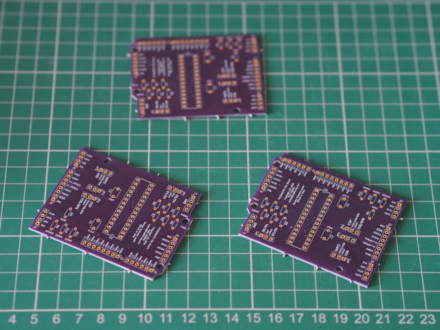
The fabricated boards, with the annoying “tabs” visible around the edges.
Having tested the continuity between different pads using a simple power plus LED plus resistor arrangement, all that remained was to get the soldering equipment out and to build myself up to the usually arduous task of fitting all the headers, resistors, capacitors and the socket. This was something of a trial in itself, but I eventually remembered the various tricks needed to coerce my soldering iron to apply the solder in a barely decent way.
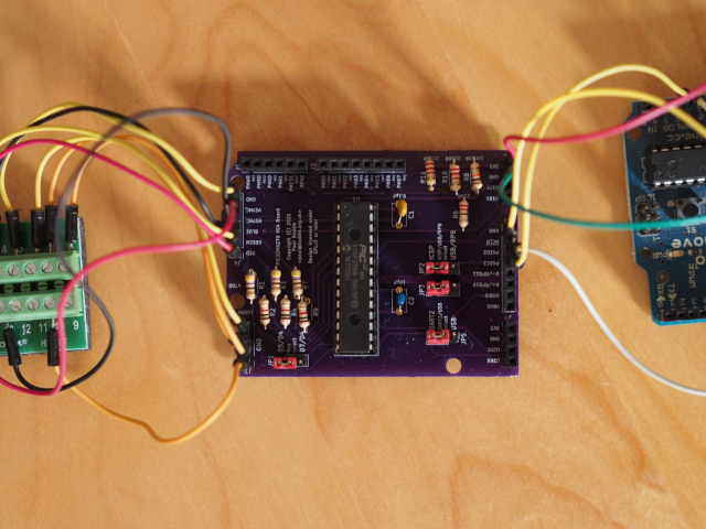
The finished board connected to the VGA terminal block and Arduino Duemilanove.
One thing I realised very quickly was that I had chosen the wrong component footprint for the resistors. In navigating the rather unreadable list provided by the inflexible component assignment dialogue within KiCad, I had chosen footprints with the pads not being sufficiently separated for the resistors I happen to have (and ones that are likely to be sold for these purposes). So, I had to raise the resistors up from the board and tuck the leads under them slightly. Despite the additional height occupied by the resistors, the capacitors and headers are already rather tall and so this workaround causes no other problems. I also discovered that placing the resistors in the compact arrangement shown, while very neat and tidy, made all the unsoldered leads rather crowded on the underside of the board and rather increased the risk of accidental solder bridging between components, at least with my soldering technique. The capacitors had appropriate footprints, however, and were less of a challenge.
What followed was another trial, mostly caused by a simple wiring up error, and lots of troubleshooting involving the programming software and circuits both on this board and on the breadboard, chasing down a non-existent programming issue. The programming circuit was actually fine, and the programming was actually being performed as normal, but in maintaining a level of doubt about the outcome of the exercise, I had run the verification operation of the programming software and had seen that it was consistently complaining about a programming error. Worryingly, this error now seemed to occur both on the manufactured board and on the breadboard, for both a microcontroller that I had used before and a completely unused one. I started to test and investigate different versions of the programming software to see if any regressions had occurred.
Eventually, I realised that the error was related to the last thing the software would do when programming the microcontroller and was related to setting a configuration register. Ignoring this and reminding myself of the UART configuration, I sought to test the example program demonstrating UART communication and found, eventually, that it worked on the breadboard. It also worked on the manufactured board, too, raising my confidence slightly. And then, while perusing my previous blog post, I realised that I had connected the VGA sync signal pins the wrong way round! Programming the VGA example program and fixing the wiring finally got me to where I should have been to begin with.
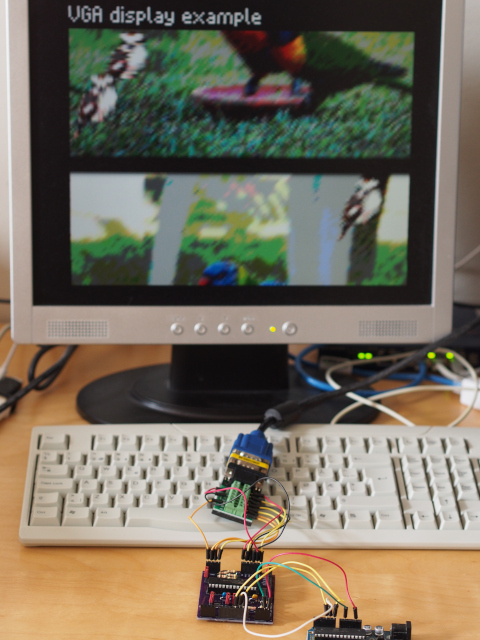
The board generating a VGA signal via a terminal block and cable, with the Arduino supplying power and acting as programmer.
The arrangement of boards required here is a bit cumbersome, although the Arduino could be replaced by a simple 3.3V power source if the appropriate software has already been programmed into the PIC32 microcontroller. As noted above, an auxiliary board could provide a VGA socket for a cable and thus eliminate the bulky terminal connector.
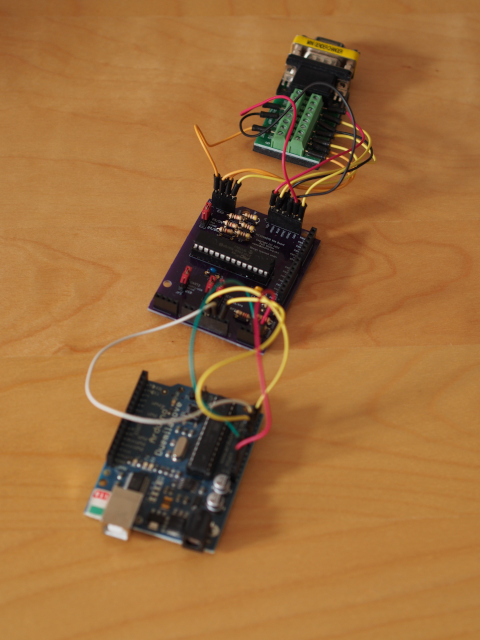
The three-board arrangement of VGA terminal block, VGA signal board, and Arduino Duemilanove.
As far as using an existing Arduino case is concerned, there are some obvious limitations and possibilities for improvement and refinement. The size and shape of the manufactured board is compatible with the case I happen to have, but where an Arduino shield would be stacked on top of the Duemilanove directly, this board necessitates that the connections be routed using wires or cables between the Arduino’s analogue header and the programming header on this board. Having mounted female headers on this board, this involves routing cables around the edge of the board, and the lack of clearance between the Arduino’s headers and the underside of this board means that there is not enough space to use jumper wires. Fortunately, breadboard jumper cables can do this job, if not entirely elegantly.
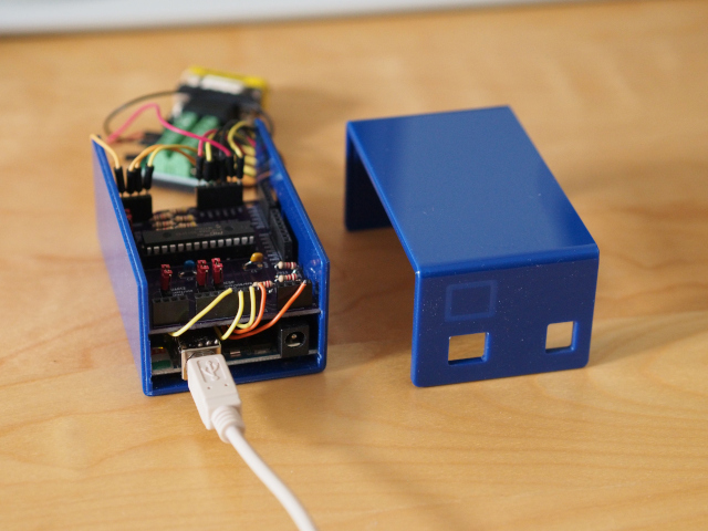
The board and the Duemilanove in a case, with the cables routing programming and power signals between the boards.
Introducing a degree of shield compatibility might be a solution to such problems, but perhaps I should not be too hard on myself. The new computer I bought in 2020 has its own compartment for cables, and this compartment is rammed full of seemingly needless, bulky cabling, presumably demonstrating the designers’ aptitude for cable management as they neglected other basic functionality one would expect from a computer case in the third decade of the twenty-first century.
There are other modifications that I might make in a second version of this board. Challenged by the layout issues, I neglected to realise that if the VGA signal resistors are fitted, some of the parallel bus pins will have their own signals mixed with others: I should have realised this and specified diodes for the various signal lines concerned. Still, with spare boards and another microcontroller to play with, I could possibly just make up a board without those resistors if I wanted to experiment with parallel mode. Since this would most likely involve driving a screen, it wouldn’t make sense to try and support that and VGA output on the same board, although I could imagine some kind of switching solution disabling one and enabling the other as appropriate.
In reflection, the outcome is satisfactory. I did spend rather too long designing, building and – especially – troubleshooting the board, and there are definitely things that are obviously wrong with it, but it has now allowed me to dismantle the original breadboard circuit, free up some jumper wires and components, and to put all of those things away properly. It has also helped me become familiar with KiCad once again, encouraged me to document more schematics, and opened the door to doing more circuit design in the future. In any case, I hope that this was a somewhat interesting view into the realisation of a long overdue project.