Another Look at VGA Signal Generation with a PIC32 Microcontroller
Thursday, November 8th, 2018Maybe some people like to see others attempting unusual challenges, things that wouldn’t normally be seen as productive, sensible or a good way to spend time and energy, things that shouldn’t be possible or viable but were nevertheless made to work somehow. And maybe they like the idea of indulging their own curiosity in such things, knowing that for potential future experiments of their own there is a route already mapped out to some kind of success. That might explain why my project to produce a VGA-compatible analogue video signal from a PIC32 microcontroller seems to attract more feedback than some of my other, arguably more useful or deserving, projects.
Nevertheless, I was recently contacted by different people inquiring about my earlier experiments. One was admittedly only interested in using Free Software tools to port his own software to the MIPS-based PIC32 products, and I tried to give some advice about navigating the documentation and to describe some of the issues I had encountered. Another was more concerned with the actual signal generation aspect of the earlier project and the usability of the end result. Previously, I had also had a conversation with someone looking to use such techniques for his project, and although he ended up choosing a different approach, the cumulative effect of my discussions with him and these more recent correspondents persuaded me to take another look at my earlier work and to see if I couldn’t answer some of the questions I had received more definitively.
Picking Over the Pieces
I was already rather aware of some of the demonstrated and potential limitations of my earlier work, these being concerned with generating a decent picture, and although I had attempted to improve the work on previous occasions, I think I just ran out of energy and patience to properly investigate other techniques. The following things were bothersome or a source of concern:
- The unevenly sized pixels
- The process of experimentation with the existing code
- Whether the microcontroller could really do other things while displaying the picture
Although one of my correspondents was very complimentary about the form of my assembly language code, I rather felt that it was holding me back, making me focus on details that should be abstracted away. It should be said that MIPS assembly language is fairly pleasant to write, at least in comparison to certain other architectures.
(I was brought up on 6502 assembly language, where there is an “accumulator” that is the only thing even approaching a general-purpose register in function, and where instructions need to combine this accumulator with other, more limited, registers to do things like accessing “zero page”: an area of memory that supports certain kinds of operations by providing the contents of locations as inputs. Everything needs to be meticulously planned, and despite odd claims that “zero page” is really one big register file and that 6502 is therefore “RISC-like”, the existence of virtual machines such as SWEET16 say rather a lot about how RISC-like the 6502 actually is. Later, I learned ARM assembly language and found it rather liberating with its general-purpose registers and uncomplicated, rather easier to use, memory access instructions. Certain things are even simpler in MIPS assembly language, whereas other conveniences from ARM are absent and demand a bit more effort from the programmer.)
Anyway, I had previously introduced functionality in C in my earlier work, mostly because I didn’t want the challenge of writing graphics routines in assembly language. So with the need to more easily experiment with different peripheral configurations, I decided to migrate the remaining functionality to C, leaving only the lowest-level routines concerned with booting and exception/interrupt handling in assembly language. This effort took me to some frustrating places, making me deal with things like linker scripts and the kind of memory initialisation that one’s compiler usually does for you but which is absent when targeting a “bare metal” environment. I shall spare you those details in this article.
I therefore spent a certain amount of effort in developing some C library functionality for dealing with the hardware. It could be said that I might have used existing libraries instead, but ignoring Microchip’s libraries that will either be proprietary or the subject of numerous complaints by those unwilling to leave that company’s “ecosystem”, I rather felt that the exercise in library design would be useful in getting reacquainted and providing me with something I would actually want to use. An important goal was minimalism, whereas my impression of libraries such as those provided by the Pinguino effort are that they try and bridge the different PIC hardware platforms and consequently accumulate features and details that do not really interest me.
The Wide Pixel Problem
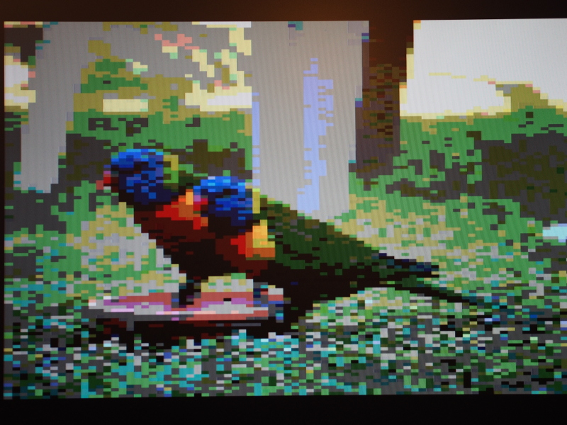
One thing that had bothered me when demonstrating a VGA signal was that the displayed images featured “wide” pixels. These are not always noticeable: one of my correspondents told me that he couldn’t see them in one of my example pictures, but they are almost certainly present because they are a feature of the mechanism used to generate the signal. Here is a crop from the example in question:

Picture detail from VGAPIC32 output
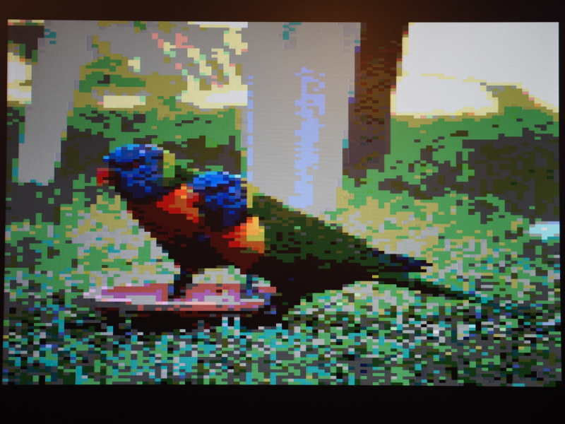
And here is the same crop with the wide pixels highlighted:
Picture detail with wide pixels highlighted
I have left the identification of all wide pixel columns to the reader! Nevertheless, it can be stated that these pixels occur in every fourth column and are especially noticeable with things like text, where at such low resolutions, the doubling of pixel widths becomes rather obvious and annoying.
Quite why this increase in pixel width was occurring became a matter I wanted to investigate. As you may recall, the technique I used to output pixels involved getting the direct memory access (DMA) controller in the PIC32 chip to “copy” the contents of memory to a hardware register corresponding to output pins. The signals from these pins were sent along the cable to the monitor. And the DMA controller was transferring data as fast as it could and thus producing pixel colours as fast as it could.
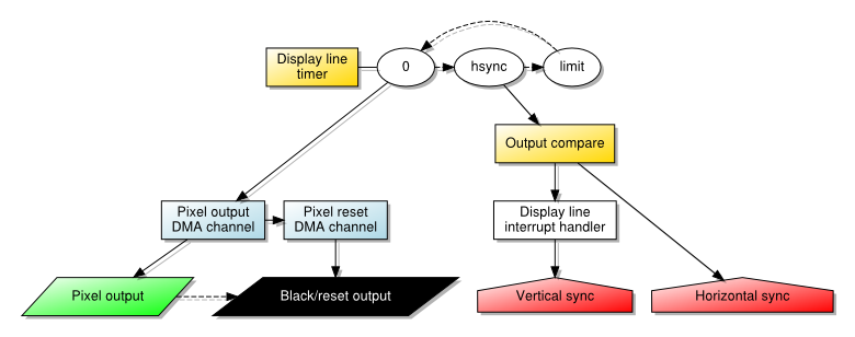
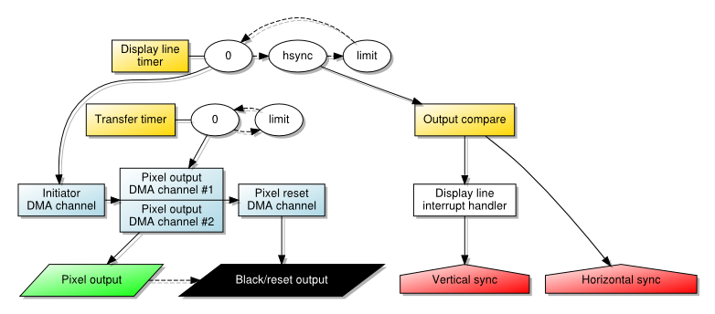
An overview of the architecture for pixel output using DMA transfer
One of my correspondents looked into the matter and confirmed that we were not imagining this problem, even employing an oscilloscope to check what was happening with the signals from the output pins. The DMA controller would, after starting each fourth pixel, somehow not be able to produce the next pixel in a timely fashion, leaving the current pixel colour unchanged as the monitor traced the picture across the screen. This would cause these pixels to “stretch” until the first pixel from the next group could be emitted.
Initially, I had thought that interrupts were occurring and the CPU, in responding to interrupt conditions and needing to read instructions, was gaining priority over the DMA controller and forcing pixel transfers to wait. Although I had specified a “cell size” of 160 bytes, corresponding to 160 pixels, I was aware that the architecture of the system would be dividing data up into four-byte “words”, and it would be natural at certain points for accesses to memory to be broken up and scheduled in terms of such units. I had therefore wanted to accommodate both the CPU and DMA using an approach where the DMA would not try and transfer everything at once, but without the energy to get this to work, I had left the matter to rest.
A Steady Rhythm
The documentation for these microcontrollers distinguishes between block and cell transfers when describing DMA. Previously, I had noted that these terms could be better described, and I think there are people who are under the impression that cells must be very limited in size and that you need to drive repeated cell transfers using various interrupt conditions to transfer larger amounts. We have seen that this is not the case: a single, large cell transfer is entirely possible, even though the characteristics of the transfer have been less than desirable. (Nevertheless, the documentation focuses on things like copying from one UART peripheral to another, arguably failing to explore the range of possible applications for DMA and to thereby elucidate the mechanisms involved.)
However, given the wide pixel effect, it becomes more interesting to introduce a steady rhythm by using smaller cell sizes and having an external event coordinate each cell’s transfer. With a single, large transfer, only one initiation event needs to occur: that produced by the timer whose period corresponds to that of a single horizontal “scanline”. The DMA channel producing pixels then runs to completion and triggers another channel to turn off the pixel output. In this scheme, the initiating condition for the cell transfer is the timer.
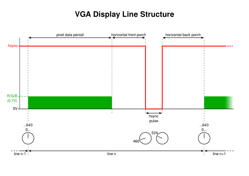
The structure of each visible display line in the VGA signal
When using multiple cells to transfer the pixel data, however, it is no longer possible to use the timer in this way. Doing so would cause the initiation of the first cell, but then subsequent cells would only be transferred on subsequent timer events. And since these events only occur once per scanline, this would see a single line’s pixel data being transferred over many scanlines instead (or, since the DMA channel would be updated regularly, we would see only the first pixel on each line being emitted, stretched across the entire line). Since the DMA mechanism apparently does not permit one kind of interrupt condition to enable a channel and another to initiate each cell transfer, we must be slightly more creative.
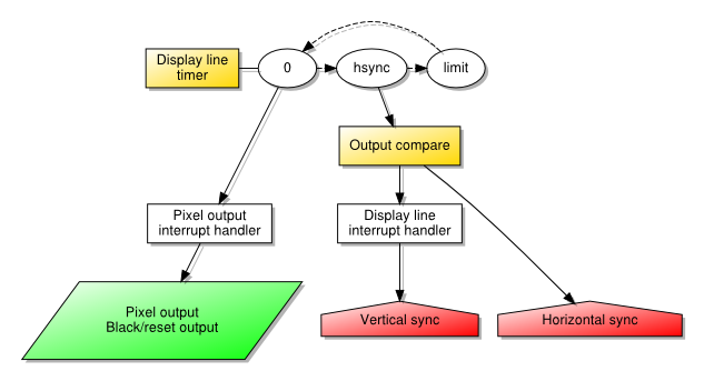
Fortunately, the solution is to chain two channels, just as we already do with the pixel-producing channel and the one that resets the output. A channel is dedicated to waiting for the line timer event, and it transfers a single black pixel to the screen before handing over to the pixel-producing channel. This channel, now enabled, has its cell transfers regulated by another interrupt condition and proceeds as fast as such a condition may occur. Finally, the reset channel takes over and turns off the output as before.
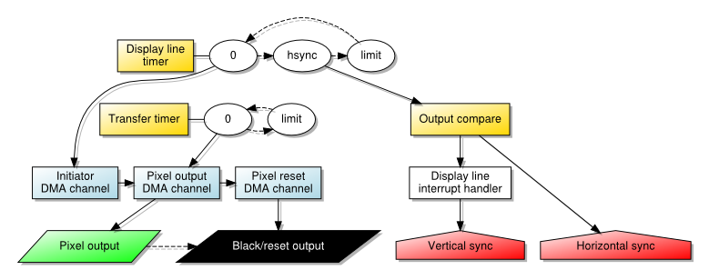
An overview of the architecture for pixel output using timed DMA transfers
The nature of the cell transfer interrupt can take various forms, but it is arguably most intuitive to use another timer for this purpose. We may set the limit of such a timer to 1, indicating that it may “wrap around” and thus produce an event almost continuously. And by configuring it to run as quickly as possible, at the frequency of the peripheral clock, it may drive cell transfers at a rate that is quick enough to hopefully produce enough pixels whilst also allowing other activities to occur between each transfer.
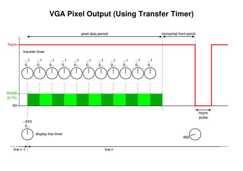
Using a timer to initiate pixel transfers for the VGA signal
One thing is worth mentioning here just to be explicit about the mechanisms involved. When configuring interrupts that are used for DMA transfers, it is the actual condition that matters, not the interrupt nor the delivery of the interrupt request to the CPU. So, when using timer events for transfers, it appears to be sufficient to merely configure the timer; it will produce the interrupt condition upon its counter “wrapping around” regardless of whether the interrupt itself is enabled.
With a cell size of a single byte, and with a peripheral clock running at half the speed of the system clock, this approach is sufficient all by itself to yield pixels with consistent widths, with the only significant disadvantage being how few of them can be produced per line: I could only manage in the neighbourhood of 80 pixels! Making the peripheral clock run as fast as the system clock doesn’t help in theory: we actually want the CPU running faster than the transfer rate just to have a chance of doing other things. Nor does it help in practice: picture stability rather suffers.
A picture of the display output from timed DMA transfers
Using larger cell sizes, we encounter the wide pixel problem, meaning that the end of a four-byte group is encountered and the transfer hangs on for longer than it should. However, larger cell sizes also introduce byte transfers at a different rate from cell transfers (at the system clock rate) and therefore risk making the last pixel produced by a cell longer than the others, anyway.
Uncovering DMA Transfers
I rather suspect that interruptions are not really responsible for the wide pixels at all, and that it is the DMA controller that causes them. Some discussion with another correspondent explored how the controller might be operating, with transfers perhaps looking something like this:
DMA read from memory
DMA write to display (byte #1)
DMA write to display (byte #2)
DMA write to display (byte #3)
DMA write to display (byte #4)
DMA read from memory
...
This would, by itself, cause a transfer pattern like this:
R____R____R____R____R____R ...
_WWWW_WWWW_WWWW_WWWW_WWWW_ ...
And thus pixel output as follows:
41234412344123441234412344 ...
=***==***==***==***==***== ... (narrow pixels as * and wide pixel components as =)
Even without any extra operations or interruptions, we would get a gap between the write operations that would cause a wider pixel. This would only get worse if the DMA controller had to update the address of the pixel data after every four-byte read and write, not being able to do so concurrently with those operations. And if the CPU were really able to interrupt longer transfers, even to obtain a single instruction to execute, it might then compete with the DMA controller in accessing memory, making the read operations even later every time.
Assuming, then, that wide pixels are the fault of the way the DMA controller works, we might consider how we might want it to work instead:
                     | ...
DMA read from memory | DMA write to display (byte #4)
                 \-> | DMA write to display (byte #1)
                     | DMA write to display (byte #2)
                     | DMA write to display (byte #3)
DMA read from memory | DMA write to display (byte #4)
                 \-> | ...
If only pixel data could be read from memory and written to the output register (and thus the display) concurrently, we might have a continuous stream of evenly-sized pixels. Such things do not seem possible with the microcontroller I happen to be using. Either concurrent reading from memory and writing to a peripheral is not possible or the DMA controller is not able to take advantage of this concurrency. But these observations did give me another idea.
Dual Channel Transfers
If the DMA controller cannot get a single channel to read ahead and get the next four bytes, could it be persuaded to do so using two channels? The intention would be something like the following:
Channel #1:                     Channel #2:
                                ...
DMA read from memory            DMA write to display (byte #4)
DMA write to display (byte #1)
DMA write to display (byte #2)
DMA write to display (byte #3)
DMA write to display (byte #4)  DMA read from memory
                                DMA write to display (byte #1)
...                             ...
This is really nothing different from the above, functionally, but the required operations end up being assigned to different channels explicitly. We would then want these channels to cooperate, interleaving their data so that the result is the combined sequence of pixels for a line:
Channel #1: 1234    1234     ...
Channel #2:     5678    5678 ...
  Combined: 1234567812345678 ...
It would seem that channels might even cooperate within cell transfers, meaning that we can apparently schedule two long transfer cells and have the DMA controller switch between the two channels after every four bytes. Here, I wrote a short test program employing text strings and the UART peripheral to see if the microcontroller would “zip up” the strings, with the following being used for single-byte cells:
Channel #1: "Adoc gi,hlo\r"
Channel #2: "n neaan el!\n"
  Combined: "And once again, hello\r\n"
Then, seeing that it did, I decided that this had a chance of also working with pixel data. Here, every other pixel on a line needs to be presented to each channel, with the first channel being responsible for the pixels in odd-numbered positions, and the second channel being responsible for the even-numbered pixels. Since the DMA controller is unable to step through the data at address increments other than one (which may be a feature of other DMA implementations), this causes us to rearrange each line of pixel data as follows:
 Displayed pixels: 123456......7890
Rearranged pixels: 135...79246...80
                   *       *
Here, the asterisks mark the start of each channel’s data, with each channel only needing to transfer half the usual amount.
The architecture involved in employing two pixel data channels with timed transfers
The documentation does, in fact, mention that where multiple channels are active with the same priority, each one is given control in turn with the controller cycling through them repeatedly. The matter of which order they are chosen, which is important for us, seems to be dependent on various factors, only some of which I can claim to understand. For instance, I suspect that if the second channel refers to data that appears before the first channel’s data in memory, it gets scheduled first when both channels are activated. Although this is not a significant concern when just trying to produce a stable picture, it does limit more advanced operations such as horizontal scrolling.
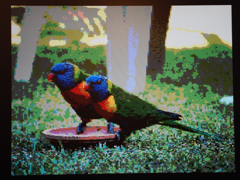
A picture of the display output from timed, dual-channel DMA transfers
As you can see, trying this technique out with timed transfers actually made a difference. Instead of only managing something approaching 80 pixels across the screen, more than 90 can be accommodated. Meanwhile, experiments with transfers going as fast as possible seemed to make no real difference, and the fourth pixel in each group was still wider than the others. Still, making the timed transfer mode more usable is a small victory worth having, I suppose.
Parallel Mode Revisited
At the start of my interest in this project, I had it in my mind that I would couple DMA transfers with the parallel mode (or Parallel Master Port) functionality in order to generate a VGA signal. Certain aspects of this, particularly gaps between pixels, made me less than enthusiastic about the approach. However, in considering what might be done to the output signal in other situations, I had contemplated the use of a flip-flop to hold output stable according to a regular tempo, rather like what I managed to achieve, almost inadvertently, when introducing a transfer timer. Until recently, I had failed to apply this idea to where it made most sense: in regulating the parallel mode signal.
Since parallel mode is really intended for driving memory devices and display controllers, various control signals are exposed via pins that can tell these external devices that data is available for their consumption. For our purposes, a flip-flop is just like a memory device: it retains the input values sampled by its input pins, and then exposes these values on its output pins when the inputs are “clocked” into memory using a “clock pulse” signal. The parallel mode peripheral in the microcontroller offers various different signals for such clock and selection pulse purposes.
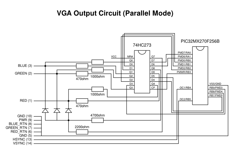
The parallel mode circuit showing connections relevant to VGA output (generic connections are not shown)
Employing the PMWR (parallel mode write) signal as the clock pulse, directing the display signals to the flip-flop’s inputs, and routing the flip-flop’s outputs to the VGA circuit solved the pixel gap problem at a stroke. Unfortunately, it merely reminded us that the wide pixel problem also affects parallel mode output, too. Although the clock pulse is able to tell an external component about the availability of a new pixel value, it is up to the external component to regulate the appearance of each pixel. A memory device does not care about the timing of incoming data as long as it knows when such data has arrived, and so such regulation is beyond the capabilities of a flip-flop.
It was observed, however, that since each group of pixels is generated at a regular frequency, the PMWR signalling frequency might be reduced by being scaled by a constant factor. This might allow some pixel data to linger slightly longer in the flip-flop and be slightly stretched. By the time the fourth pixel in a group arrives, the time allocated to that pixel would be the same as those preceding it, thus producing consistently-sized pixels. I imagine that a factor of 8/9 might do the trick, but I haven’t considered what modification to the circuit might be needed or whether it would all be too complicated.
Recognising the Obvious
When people normally experiment with video signals from microcontrollers, one tends to see people writing code to run as efficiently as is absolutely possible – using assembly language if necessary – to generate the video signal. It may only be those of us using microcontrollers with DMA peripherals who want to try and get the DMA hardware to do the heavy lifting. Indeed, those of us with exposure to display peripherals provided by system-on-a-chip solutions feel almost obliged to do things this way.
But recent discussions with one of my correspondents made me reconsider whether an adequate solution might be achieved by just getting the CPU to do the work of transferring pixel data to the display. Previously, another correspondent had indicated that it this was potentially tricky, and that getting the timings right was more difficult than letting the hardware synchronise the different mechanisms – timer and DMA – all by itself. By involving the CPU and making it run code, the display line timer would need to generate an interrupt that would be handled, causing the CPU to start running a loop to copy data from the framebuffer to the output port.
An overview of the architecture with the CPU driving transfers of pixel data
This approach puts us at the mercy of how the CPU handles and dispatches interrupts. Being somewhat conservative about the mechanisms more generally available on various MIPS-based products, I tend to choose a single interrupt vector and then test for the different conditions. Since we need as little variation as possible in the latency between a timer event occurring and the pixel data being generated, I test for that particular event before even considering anything else. Then, a loop of the following form is performed:
    for (current = line_data; current < end; current++)
        *output_port = *current;
Here, the line data is copied byte by byte to the output port. Some adornments are necessary to persuade the compiler to generate code that writes the data efficiently and in order, but there is nothing particularly exotic required and GCC does a decent job of doing what we want. After the loop, a black/reset pixel is generated to set the appropriate output level.
One concern that one might have about using the CPU for such long transfers in an interrupt handler is that it ties up the CPU, preventing it from doing other things, and it also prevents other interrupt requests from being serviced. In a system performing a limited range of activities, this can be acceptable: there may be little else going on apart from updating the display and running programs that access the display; even when other activities are incorporated, they may accommodate being relegated to a secondary status, or they may instead take priority over the display in a way that may produce picture distortion but only very occasionally.
Many of these considerations applied to systems of an earlier era. Thinking back to computers like the Acorn Electron – a 6502-based system that formed the basis of my first sustained experiences with computing – it employs a display controller that demands access to the computer’s RAM for a certain amount of the time dedicated to each video frame. The CPU is often slowed down or even paused during periods of this display controller’s activity, making programs slower than they otherwise would be, and making some kinds of input and output slightly less reliable under certain circumstances. Nevertheless, with certain kinds of additional hardware, the possibility is present for such hardware to interrupt the CPU and to override the display controller that would then produce “snow” or noise on the screen as a consquence of this high-priority interruption.
Such issues cause us to consider the role of the DMA controller in our modern experiment. We might well worry about loading the CPU with lots of work, preventing it from doing other things, but what if the DMA controller dominates the system in such a way that it effectively prevents the CPU from doing anything productive anyway? This would be rather similar to what happens with the Electron and its display controller.
So, evaluating a CPU-driven solution seems to be worthwhile just to see whether it produces an acceptable picture and whether it causes unacceptable performance degradation. My recent correspondence also brought up the assertion that the RAM and flash memory provided by PIC32 microcontrollers can be accessed concurrently. This would actually mitigate contention between DMA and any programs running from flash memory, at least until the point that accesses to RAM needed to be performed by those programs, meaning that we might expect some loss of program performance by shifting the transfer burden to the CPU.
(Again, I am reminded of the Electron whose ROM could be accessed at full speed but whose RAM could only be accessed at half speed by the CPU but at full speed by the display controller. This might have been exploited by software running from ROM, or by a special kind of RAM installed and made available at the right place in memory, but the 6502 favours those zero-page instructions mentioned earlier, forcing RAM access and thus contention with the display controller. There were upgrades to mitigate this by providing some dedicated memory for zero page, but all of this is really another story for another time.)
Ultimately, having accepted that the compiler would produce good-enough code and that I didn’t need to try more exotic things with assembly language, I managed to produce a stable picture.
A picture of the display output from CPU-driven pixel data transfers
Maybe I should have taken this obvious path from the very beginning. However, the presence of DMA support would have eventually caused me to investigate its viability for this application, anyway. And it should be said that the performance differences between the CPU-based approach and the DMA-based approaches might be significant enough to argue in favour of the use of DMA for some purposes.
Observations and Conclusions
What started out as a quick review of my earlier work turned out to be a more thorough study of different techniques and approaches. I managed to get timed transfers functioning, revisited parallel mode and made it work in a fairly acceptable way, and I discovered some optimisations that help to make certain combinations of techniques more usable. But what ultimately matters is which approaches can actually be used to produce a picture on a screen while programs are being run at the same time.
To give the CPU more to do, I decided to implement some graphical operations, mostly copying data to a framebuffer for its eventual transfer as pixels to the display. The idea was to engage the CPU in actual work whilst also exercising access to RAM. If significant contention between the CPU and DMA controller were to occur, the effects would presumably be visible on the screen, potentially making the chosen configuration unusable.
Although some approaches seem promising on paper, and they may even produce promising results when the CPU is doing little more than looping and decrementing a register to introduce a delay, these approaches may produce less than promising results under load. The picture may start to ripple and stretch, and under “real world” load, the picture may seem noisy and like a badly-tuned television (for those who remember the old days of analogue broadcast signals).
Two approaches seem to remain robust, however: the use of timed DMA transfers, and the use of the CPU to do all the transfer work. The former is limited in terms of resolution and introduces complexity around the construction of images in the framebuffer, at least if optimised as much as possible, but it seems to allow more work to occur alongside the update of the display, and the reduction in resolution also frees up RAM for other purposes for those applications that need it. Meanwhile, the latter provides the resolution we originally sought and offers a straightforward framebuffer arrangement, but it demands more effort from the CPU, slowing things down to the extent that animation practically demands double buffering and thus the allocation of even more RAM for display purposes.
But both of these seemingly viable approaches produce consistent pixel widths, which is something of a happy outcome given all the effort to try and fix that particular problem. One can envisage accommodating them both within a system given that various fundamental system properties (how fast the system and peripheral clocks are running, for example) are shared between the two approaches. Again, this is reminiscent of microcomputers where a range of display modes allowed developers and users to choose the trade-off appropriate for them.
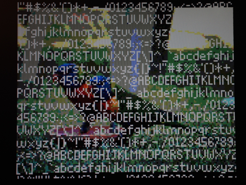
A demonstration of text plotting at a resolution of 160x128
Having investigated techniques like hardware scrolling and sprite plotting, it is tempting to keep developing software to demonstrate the techniques described in this article. I am even tempted to design a printed circuit board to tidy up my rather cumbersome breadboard arrangement. And perhaps the library code I have written can be used as the basis for other projects.
It is remarkable that a home-made microcontroller-based solution can be versatile enough to demonstrate aspects of simple computer systems, possibly even making it relevant for those wishing to teach or to learn about such things, particularly since all the components can be connected together relatively easily, with only some magic happening in the microcontroller itself. And with such potential, maybe this seemingly pointless project might have some meaning and value after all!
Update
Although I can’t embed video files of any size here, I have made a “standard definition” video available to demonstrate scrolling and sprites. I hope it is entertaining and also somewhat illustrative of the kind of thing these techniques can achieve.