On Planet Debian there seems to be quite a few regularly-posted articles summarising the work done by various people in Free Software over the month that has most recently passed. I thought it might be useful, personally at least, to review the different things I have been doing over the past year. The difference between this article and many of those others is that the work I describe is not commissioned or generally requested by others, instead relying mainly on my own motivation for it to happen. The rate of progress can vary somewhat as a result.
Learning KiCad
Over the years, I have been playing around with Arduino boards, sensors, displays and things of a similar nature. Although I try to avoid buying more things to play with, sometimes I manage to acquire interesting items regardless, and these aren’t always ready to use with the hardware I have. Last December, I decided to buy a selection of electronics-related items for interfacing and experimentation. Some of these items have yet to be deployed, but others were bought with the firm intention of putting different “spare” pieces of hardware to use, or at least to make them usable in future.
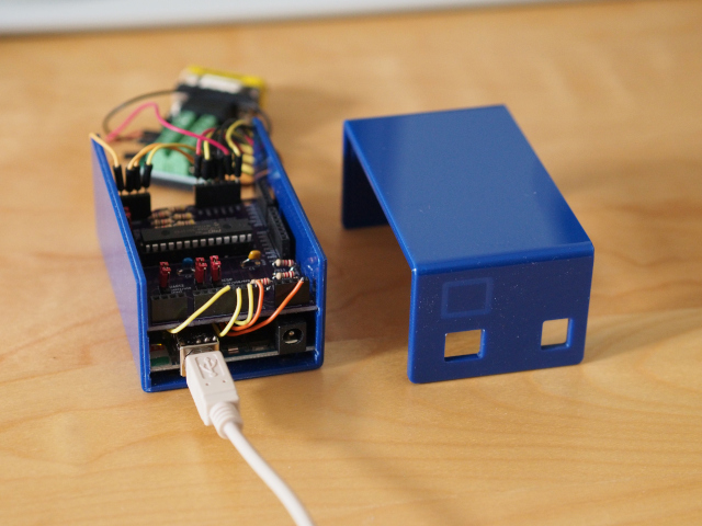
One thing that sits in this category of spare, potentially-usable hardware is a display circuit board that was once part of a desk telephone, featuring a two-line, bitmapped character display, driven by the Hitachi HD44780 LCD controller. It turns out that this hardware is so common and mundane that the Arduino libraries already support it, but the problem for me was being able to interface it to the Arduino. The display board uses a cable with a connector that needs a special kind of socket, and so some research is needed to discover the kind of socket needed and how this might be mounted on something else to break the connections out for use with the Arduino.
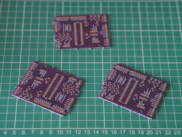
Fortunately, someone else had done all this research quite some time ago. They had even designed a breakout board to hold such a socket, making it available via the OSH Park board fabricating service. So, to make good on my plan, I ordered the mandatory minimum of three boards, also ordering some connectors from Mouser. When all of these different things arrived, I soldered the socket to the board along with some headers, wired up a circuit, wrote a program to use the LiquidCrystal Arduino library, and to my surprise it more or less worked straight away.
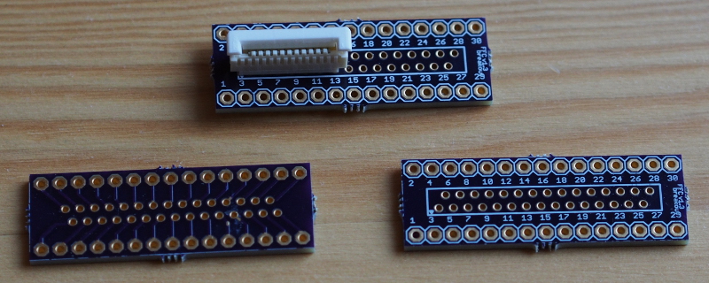
Breakout board for the Molex 52030 connector
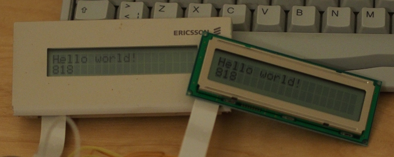
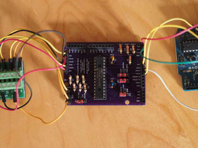
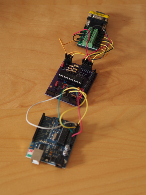
Hitachi HD44780 LCD display boards driven by an Arduino
This satisfying experience led me to consider other boards that I might design and get made. Previously, I had only made a board for the Arduino using Fritzing and the Fritzing Fab service, and I had held off looking at other board design solutions, but this experience now encouraged me to look again. After some evaluation of the gEDA tools, I decided that I might as well give KiCad a try, given that it seems to be popular in certain “open source hardware” circles. And after a fair amount of effort familiarising myself with it, with a degree of frustration finding out how to do certain things (and also finding up-to-date documentation), I managed to design my own rather simple board: a breakout board for the Acorn Electron cartridge connector.
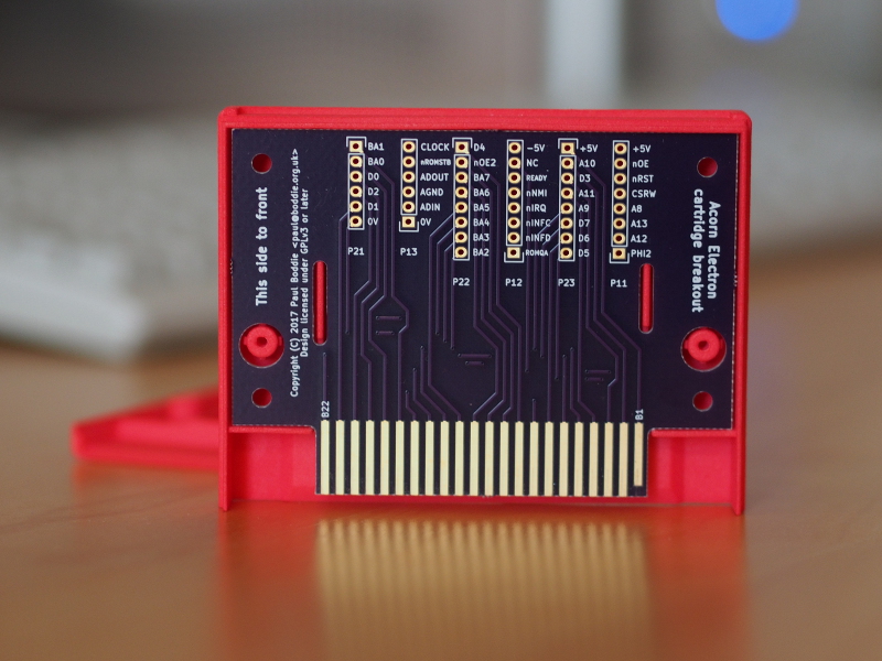
Acorn Electron cartridge breakout board (in 3D-printed case section)
In the back of my mind, I have vague plans to do other boards in future, but doing this kind of work can soak up a lot of time and be rather frustrating: you almost have to get into some modified mental state to work efficiently in KiCad. And it isn’t as if I don’t have other things to do. But at least I now know something about what this kind of work involves.
Retro and Embedded Hardware
With the above breakout board in hand, a series of experiments were conducted to see if I could interface various circuits to the Acorn Electron microcomputer. These mostly involved 7400-series logic chips (ICs, integrated circuits) and featured various logic gates and counters. Previously, I had re-purposed an existing ROM cartridge design to break out signals from the computer and make it access a single flash memory chip instead of two ROM chips.
With a dedicated prototyping solution, I was able to explore the implementation of that existing board, determine various aspects of the signal timings that remained rather unclear (despite being successfully handled by the existing board’s logic), and make it possible to consider a dedicated board for a flash memory cartridge. In fact, my brother, David, also wanting to get into board design, later adapted the prototyping cartridge to make such a board.
But this experimentation also encouraged me to tackle some other items in the electronics shipment: the PIC32 microcontrollers that I had acquired because they were MIPS-based chips, with somewhat more built-in RAM than the Atmel AVR-based chips used by the average Arduino, that could also be used on a breadboard. I hoped that my familiarity with the SoC (system-on-a-chip) in the Ben NanoNote – the Ingenic JZ4720 – might confer some benefits when writing low-level code for the PIC32.
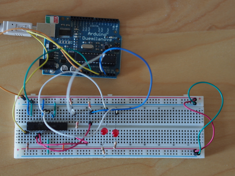
PIC32 on breadboard with Arduino programming circuit (and some LEDs for diagnostic purposes)
I do not need to reproduce an account of my activities here, given that I wrote about the effort involved in getting started with the PIC32 earlier in the year, and subsequently described an unusual application of such a microcontroller that seemed to complement my retrocomputing interests. I have since tried to make that particular piece of work more robust, but deducing the actual behaviour of the hardware has been frustrating, the documentation can be vague when it needs to be accurate, and much of the community discussion is focused on proprietary products and specific software tools rather than techniques. Maybe this will finally push me towards investigating programmable logic solutions in the future.
Compiling a Python-like Language
As things actually happened, the above hardware activities were actually distractions from something I have been working on for a long time. But at this point in the article, this can be a diversion from all the things that seem to involve hardware or low-level software development. Many years ago, I started writing software in Python. Over the years since, alternative implementations of the Python language (the main implementation being CPython) have emerged and seen some use, some continuing to be developed to this day. But around fifteen years ago, it became a bit more common for people to consider whether Python could be compiled to something that runs more efficiently (and more quickly).
I followed some of these projects enthusiastically for a while. Starkiller promised compilation to C++ but never delivered any code for public consumption, although the associated academic thesis might have prompted the development of Shed Skin which does compile a particular style of Python program to C++ and is available as Free Software. Meanwhile, PyPy elevated to prominence the notion of writing a language and runtime library implementation in the language itself, previously seen with language technologies like Slang, used to implement Squeak/Smalltalk.
Although other projects have also emerged and evolved to attempt the compilation of Python to lower-level languages (Pyrex, Cython, Nuitka, and so on), my interests have largely focused on the analysis of programs so that we may learn about their structure and behaviour before we attempt to run them, this alongside any benefits that might be had in compiling them to something potentially faster to execute. But my interests have also broadened to consider the evolution of the Python language since the point fifteen years ago when I first started to think about the analysis and compilation of Python. The near-mythical Python 3000 became a real thing in the form of the Python 3 development branch, introducing incompatibilities with Python 2 and fragmenting the community writing software in Python.
With the risk of perfectly usable software becoming neglected, its use actively (and destructively) discouraged, it becomes relevant to consider how one might take control of one’s software tools for long-term stability, where tools might be good for decades of use instead of constantly changing their behaviour and obliging their users to constantly change their software. I expressed some of my thoughts about this earlier in the year having finally reached a point where I might be able to reflect on the matter.
So, the result of a great deal of work, informed by experiences and conversations over the years related to previous projects of my own and those of others, is a language and toolchain called Lichen. This language resembles Python in many ways but does not try to be a Python implementation. The toolchain compiles programs to C which can then be compiled and executed like “normal” binaries. Programs can be trivially cross-compiled by any available C cross-compilers, too, which is something that always seems to be a struggle elsewhere in the software world. Unlike other Python compilers or implementations, it does not use CPython’s libraries, nor does it generate in “longhand” the work done by the CPython virtual machine.
One might wonder why anyone should bother developing such a toolchain given its incompatibility with Python and a potential lack of any other compelling reason for people to switch. Given that I had to accept some necessary reductions in the original scope of the project and to limit my level of ambition just to feel remotely capable of making something work, one does need to ask whether the result is too compromised to be attractive to others. At one point, programs manipulating integers were slower when compiled than when they were run by CPython, and this was incredibly disheartening to see, but upon further investigation I noticed that CPython effectively special-cases integer operations. The design of my implementation permitted me to represent integers as tagged references – a classic trick of various language implementations – and this overturned the disadvantage.
For me, just having the possibility of exploring alternative design decisions is interesting. Python’s design is largely done by consensus, with pronouncements made to settle disagreements and to move the process forward. Although this may have served the language well, depending on one’s perspective, it has also meant that certain paths of exploration have not been followed. Certain things have been improved gradually but not radically due to backwards compatibility considerations, this despite the break in compatibility between the Python 2 and 3 branches where an opportunity was undoubtedly lost to do greater things. Lichen is an attempt to explore those other paths without having to constantly justify it to a group of people who may regard such exploration as hostile to their own interests.
Lichen is not really complete: it needs floating point number and other useful types; its library is minimal; it could be made more robust; it could be made more powerful. But I find myself surprised that it works at all. Maybe I should have more confidence in myself, especially given all the preparation I did in trying to understand the good and bad aspects of my previous efforts before getting started on this one.
Developing for MIPS-based Platforms
A couple of years ago I found myself wondering if I couldn’t write some low-level software for the Ben NanoNote. One source of inspiration for doing this was “The CI20 bare-metal project“: a series of blog articles discussing the challenges of booting the MIPS Creator CI20 single-board computer. The Ben and the CI20 use CPUs (or SoCs) from the same family: the Ingenic JZ4720 and JZ4780 respectively.
For the Ben, I looked at the different boot payloads, principally those written to support booting from a USB host, but also the version of U-Boot deployed on the Ben. I combined elements of these things with the framebuffer driver code from the Linux kernel supporting the Ben, and to my surprise I was able to get the device to boot up and show a pattern on the screen. Progress has not always been steady, though.
For a while, I struggled to make the CPU leave its initial exception state without hanging, and with the screen as my only debugging tool, it was hard to see what might have been going wrong. Some careful study of the code revealed the problem: the code I was using to write to the framebuffer was using the wrong address region, meaning that as soon as an attempt was made to update the contents of the screen, the CPU would detect a bad memory access and an exception would occur. Such exceptions will not be delivered in the initial exception state, but with that state cleared, the CPU will happily trigger a new exception when the program accesses memory it shouldn’t be touching.
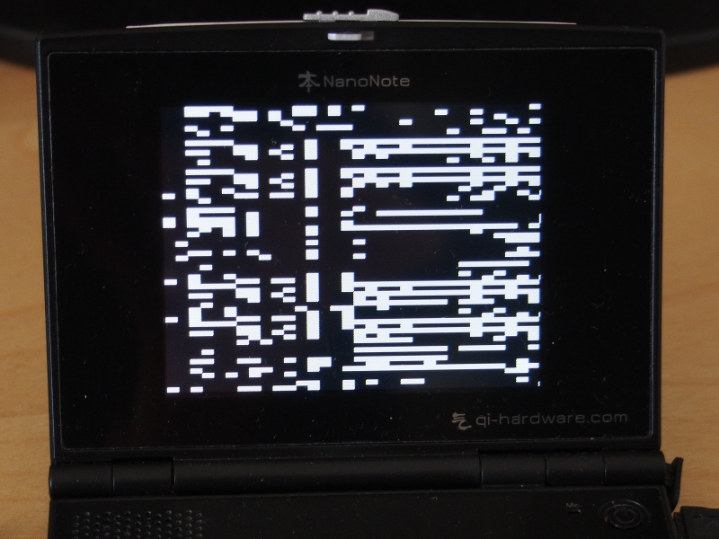
Debugging low-level code on the Ben NanoNote (the hard way)
I have since plodded along introducing user mode functionality, some page table initialisation, trying to read keypresses, eventually succeeding after retracing my steps and discovering my errors along the way. Maybe this will become a genuinely useful piece of software one day.
But one useful purpose this exercise has served is that of familiarising myself with the way these SoCs are organised, the facilities they provide, how these may be accessed, and so on. My brother has the Letux 400 notebook containing yet another SoC in the same family, the JZ4730, which seems to be almost entirely undocumented. This notebook has proven useful under certain circumstances. For instance, it has been used as a kind of appliance for document scanning, driving a multifunction scanner/printer over USB using the enduring SANE project’s software.
However, the Letux 400 is already an old machine, with products based on this hardware platform being almost ten years old, and when originally shipped it used a 2.4 series Linux kernel instead of a more recent 2.6 series kernel. Like many products whose software is shipped as “finished”, this makes the adoption of newer software very difficult, especially if the kernel code is not “upstreamed” or incorporated into the official Linux releases.
As software distributions such as Debian evolve, they depend on newer kernel features, but if a device is stuck on an older kernel (because the special functionality that makes it work on that device is specific to that kernel) then the device, unable to run the newer kernels, gradually becomes unable to run newer versions of the distribution as well. Thus, Debian Etch was the newest distribution version that would work on the 2.4 kernel used by the Letux 400 as shipped.
Fortunately, work had been done to make a 2.6 series kernel work on the Letux 400, and this made Debian Lenny functional. But time passes and even this is now considered ancient. Although David was running some software successfully, there was other software that really needed a newer distribution to be able to run, and this meant considering what it might take to support Debian Squeeze on the hardware. So he set to work adding patches to the 2.6.24 kernel to try and take it within the realm of Squeeze support, making it beyond the bare minimum of 2.6.29 and into the “release candidate” territory of 2.6.30. And this was indeed enough to run Squeeze on the notebook, at least supporting the devices needed to make the exercise worthwhile.
Now, at a much earlier stage in my own experiments with the Ben NanoNote, I had tried without success to reproduce my results on the Letux 400. And I had also made a rather tentative effort at modifying Ben NanoNote kernel drivers to potentially work with the Letux 400 from some 3.x kernel version. David’s success in updating the kernel version led me to look again at the tasks of familiarising myself with kernel drivers, machine details and of supporting the Letux 400 in even newer kernels.
The outcome of this is uncertain at present. Most of the work on updating the drivers and board support has been done, but actual testing of my work still needs to be done, something that I cannot really do myself. That might seem strange: why start something I cannot finish by myself? But how I got started in this effort is also rather related to the topic of the next section.
The MIPS Creator CI20 and L4/Fiasco.OC
Low-level programming on the Ben NanoNote is frustrating unless you modify the device and solder the UART connections to the exposed pads in the battery compartment, thereby enabling a serial connection and allowing debugging information to be sent to a remote display for perusal. My soldering skills are not that great, and I don’t want to damage my device. So debugging was a frustrating exercise. Since I felt that I needed a bit more experience with the MIPS architecture and the Ingenic SoCs, it occurred to me that getting a CI20 might be the way to go.
I am not really a supporter of Imagination Technologies, producer of the CI20, due to the company’s rather hostile attitude towards Free Software around their PowerVR technologies, meaning that of the different graphics acceleration chipsets, PowerVR has been increasingly isolated as a technology that is consistently unsupportable by Free Software drivers. However, the CI20 is well-documented and has been properly supported with Free Software, apart from the PowerVR parts of the hardware, of course. Ingenic were seemingly persuaded to make the programming manual for the JZ4780 used by the CI20 publicly available, unlike the manuals for other SoCs in that family. And the PowerVR hardware is not actually needed to be able to use the CI20.
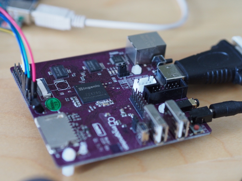
The MIPS Creator CI20 single-board computer
I had hoped that the EOMA68 campaign would have offered a JZ4775 computer card, and that the campaign might have delivered such a card by now, but with both of these things not having happened I took the plunge and bought a CI20. There were a few other reasons for doing so: I wanted to see how a single-board computer with a decent amount of RAM (1GB) might perform as a working desktop machine; having another computer to offload certain development and testing tasks, rather than run virtual machines, would be useful; I also wanted to experiment with and even attempt to port other operating systems, loosening my dependence on the Linux monoculture.
One of these other operating systems involves two components: the Fiasco.OC microkernel and the L4 Runtime Environment (L4Re). Over the years, microkernels in the L4 family have seen widespread use, and at one point people considered porting GNU Hurd to one of the L4 family microkernels from the Mach microkernel it then used (and still uses). It seems to me like something worth looking at more closely, and fortunately it also seemed that this software combination had been ported to the CI20. However, it turned out that my expectations of building an image, testing the result, and then moving on to developing interesting software were a little premature.
The first real problem was that GCC produced position-independent code that was not called correctly. This meant that upon trying to get the addresses of functions, the program would end up loading garbage addresses and trying to call any code that might be there at those addresses. So some fixes were required. Then, it appeared that the JZ4780 doesn’t support a particular MIPS instruction, meaning that the CPU would encounter this instruction and cause an exception. So, with some guidance, I wrote a handler to decode the instruction and generate the rather trivial result that the instruction should produce. There were also some more generic problems with the microkernel code that had previously been patched but which had not appeared in the upstream repository. But in the end, I got the “hello” program to run.
With a working foundation I tried to explore the hardware just as I had done with the Ben NanoNote, attempting to understand things like the clock and power management hardware, general purpose input/output (GPIO) peripherals, and also the Inter-Integrated Circuit (I2C) peripherals. Some assistance was available in the form of Linux kernel driver code, although the style of code can vary significantly, and it also takes time to “decode” various mechanisms in the Linux code and to unpick the useful bits related to the hardware. I had hoped to get further, but in trying to use the I2C peripherals to talk to my monitor using the DDC protocol, I found that the data being returned was not entirely reliable. This was arguably a distraction from the more interesting task of enabling the display, given that I know what resolutions my monitor supports.
However, all this hardware-related research and detective work at least gave me an insight into mechanisms – software and hardware – that would inform the effort to “decode” the vendor-written code for the Letux 400, making certain things seem a lot more familiar and increasing my confidence that I might be understanding the things I was seeing. For example, the JZ4720 in the Ben NanoNote arranges its hardware registers for GPIO configuration and access in a particular way, but the code written by the vendor for the JZ4730 in the Letux 400 accesses GPIO registers in a different way.
Initially, I might have thought that I was missing some important detail: are the two products really so different, and if not, then why is the code so different? But then, looking at the JZ4780, I encountered another scheme for GPIO register organisation that is different again, but which does have similarities to the JZ4730. With the JZ4780 being publicly documented, the code for the Letux 400 no longer seemed quite so bizarre or unfathomable. With more experience, it is possible to have a little more confidence in one’s understanding of the mechanisms at work.
I would like to spend a bit more time looking at microkernels and alternatives to Linux. While many people presumably think that Linux is running on everything and has “won”, it is increasingly likely that the Linux one sees on devices does not completely control the hardware and is, in fact, virtualised or confined by software systems like L4/Fiasco.OC. I also have reservations about the way Linux is developed and how well it is able to handle the demands of its proliferation onto every kind of device, many of them hooked up to the Internet and being left to fend for themselves.
Developing imip-agent
Alongside Lichen, a project that has been under development for the last couple of years has been imip-agent, allowing calendar-based scheduling activities to be integrated with mail transport agents. I haven’t been able to spend quite as much time on imip-agent this year as I might have liked, although I will also admit that I haven’t always been motivated to spend much time on it, either. Still, there have been brief periods of activity tidying up, fixing, or improving the code. And some interest in packaging the software led me to reconsider some of the techniques used to deploy the software, in particular the way scheduling extensions are discovered, and the way the system configuration is processed (since Debian does not want “executable scripts” in places like /etc, even if those scripts just contain some simple configuration setting definitions).
It is perhaps fairly typical that a project that tries to assess the feasibility of a concept accumulates the necessary functionality in order to demonstrate that it could do a particular task. After such an initial demonstration, the effort of making the code easier to work with, more reliable, more extensible, must occur if further progress is to be made. One intervention that kept imip-agent viable as a project was the introduction of a test suite to ensure that the basic functionality did indeed work. There were other architectural details that I felt needed remedying or improving for the code to remain manageable.
Recently, I have been refining the parts of the code that support editing of calendar objects and the exchange of updates caused by changes to calendar events. Such work is intended to make the Web client easier to understand and to expose such functionality to proper testing. One side-effect of this may be the introduction of a text-based client for people using e-mail programs like Mutt, as well as a potentially usable library for other mail clients. Such tidying up and fixing does not show off fancy new features or argue the case for developing such software in the first place, but I suppose it makes me feel better about the software I have written.
Whither Moin?
There are probably plenty of other little projects of my own that I have started or at least contemplated this year. And there are also projects that are not mine but which I use and which have had contributions from me over the years. One of these is the MoinMoin wiki software that powers a number of Free Software and other Web sites where collaborative editing is made available to the communities involved. I use MoinMoin – or Moin for short – to publish content on the Web myself, and I have encouraged others to use it in the past. However, it worries me now that the level of maintenance it is receiving has fallen to a level where updates for faults in the software are not likely to be forthcoming and where it is no longer clear where such updates should be coming from.
Earlier in the year, having previously read queries about the static export output from Moin, which can be rather basic and not necessarily resemble the appearance of the wiki such output has come from, I spent some time considering my own use of Moin for documentation publishing. For some of my projects, I don’t take advantage of the “through the Web” editing of the solution when publishing the public documentation. Instead, I use Moin locally, store the pages in a separate repository, and then make page packages that get installed on a public instance of Moin. This means that I do not have to worry about Web-based authentication and can just have a wiki as a read-only resource.
Obviously, the parts of Moin that I really need here are just the things that parse the wiki formatting (which I regard as more usable than other document markup formats in various respects) and that format the content as HTML. If I could format it as static content with some pages, some stylesheets, some images, with some Web server magic to make the URLs look nice, then that would probably be sufficient. For some things like the automatic generation of SVG from Graphviz-format files, I would also need to have the relevant parsers available, too. Having a complete Web framework, which is what Moin really is, is rather unnecessary with these diminished requirements.
But I do use Moin as a full wiki solution as well, and so it made me wonder whether I shouldn’t try and bring it up to date. Of course, there is already the MoinMoin 2.0 effort that was intended to modernise and tidy up the software, but since this effort made a clean break from Moin 1.x, it was never an attractive choice for those people already using Moin in anything more than a basic sense. Since there wasn’t an established API for extensions, it was not readily usable for many existing sites that rely on such extensions. In a way, Moin 2 has suffered from something that Python 3 only avoided by having a lot more people working on it, including people being paid to work on it, together with a policy of openly shaming those people who had made Python 2 viable – by developing software for it – into spending time migrating their code to Python 3.
I don’t have an obvious plan of action here. Moin perhaps illustrates the fundamental problem facing many Free Software projects, this being a theme that I have discussed regularly this year: how they may remain viable by having people able to dedicate their time to writing and maintaining Free Software without this work being squeezed in around the edges of people’s “actual work” and thus burdening them with yet another obligation in their lives, particularly one that is not rewarded by a proper appreciation of the sacrifice being made.
Plenty of individuals and organisations benefit from Moin, but we live in an age of “comparison shopping” where people will gladly drop one thing if someone offers them something newer and shinier. This is, after all, how everyone ends up using “free” services where the actual costs are hidden. To their credit, when Moin needed to improve its password management, the Python Software Foundation stepped up and funded this work rather than dropping Moin, which is what I had expected given certain Python community attitudes. Maybe other, more well-known organisations that use Moin also support its development, but I don’t really see much evidence of it.
Maybe they should consider doing so. The notion that something else will always come along, developed by some enthusiastic developer “scratching their itch”, is misguided and exploitative. And a failure to sustain Free Software development can only undermine Free Software as a resource, as an activity or a cause, and as the basis of many of those organisations’ continued existence. Many of us like developing Free Software, as I hope this article has shown, but motivation alone does not keep that software coming forever.