Paul Boddie's Free Software-related blog
Paul's activities and perspectives around Free Software
Evaluating PIC32 for Hardware Experiments
Some time ago I became aware of the PIC32 microcontroller platform, perhaps while following various hardware projects, pursuing hardware-related interests, and looking for pertinent documentation. Although I had heard of PIC microcontrollers before, my impression of them was that they were mostly an alternative to other low-end computing products like the Atmel AVR series, but with a development ecosystem arguably more reliant on its vendor than the Atmel products for which tools like avr-gcc and avrdude exist as Free Software and have gone on to see extensive use, perhaps most famously in connection with the Arduino ecosystem.
What made PIC32 stand out when I first encountered it, however, was that it uses the MIPS32 instruction set architecture instead of its own specialised architecture. Consequently, instead of being reliant on the silicon vendor and random third-party tool providers for proprietary tools, the possibility of using widely-used Free Software tools exists. Moreover, with a degree of familiarity with MIPS assembly language, thanks to the Ben NanoNote, I felt that there might be an opportunity to apply some of my elementary skills to another MIPS-based system and gain some useful experience.
Some basic investigation occurred before I made any attempt to acquire hardware. As anyone having to pay attention to the details of hardware can surely attest, it isn’t much fun to obtain something only to find that some necessary tool required for the successful use of that hardware happens to be proprietary, only works on proprietary platforms, or is generally a nuisance in some way that makes you regret the purchase. Looking around at various resources such as the Pinguino Web site gave me some confidence that there were people out there using PIC32 devices with Free Software. (Of course, the eventual development scenario proved to be different from that envisaged in these initial investigations, but previous experience has taught me to expect that things may not go as originally foreseen.)
Some Discoveries
So that was perhaps more than enough of an introduction, given that I really want to focus on some of my discoveries in using my acquired PIC32 devices, hoping that writing them up will help others to use Free Software with this platform. So, below, I will present a few discoveries that may well, for all I know, be “obvious” to people embedded in the PIC universe since it began, or that might be “superfluous” to those happy that Microchip’s development tools can obscure the operation of the hardware to offer a simpler “experience”.
I should mention at this point that I chose to acquire PDIP-profile products for use with a solderless breadboard. This is the level of sophistication at which the Arduino products mostly operate and it allows convenient prototyping involving discrete components and other electronic devices. The evidence from the chipKIT and Pinguino sites suggested that it would be possible to set up a device on a breadboard, wire it up to a power supply with a few supporting components, and then be able to program it. (It turned out that programming involved another approach than indicated by that latter reference, however.)
The 28-pin product I elected to buy was the PIC32MX270F256B-50/SP. I also bought some capacitors that were recommended for wiring up the device. In the picture below, you can just about see the capacitor connecting two of the pins, and there is also a resistor pulling up one of the pins. I recommend obtaining a selection of resistors of different values so as to be able to wire up various circuits as you encounter them. Note that the picture does not show a definitive wiring guide: please refer to the product documentation or to appropriate project documentation for such things.
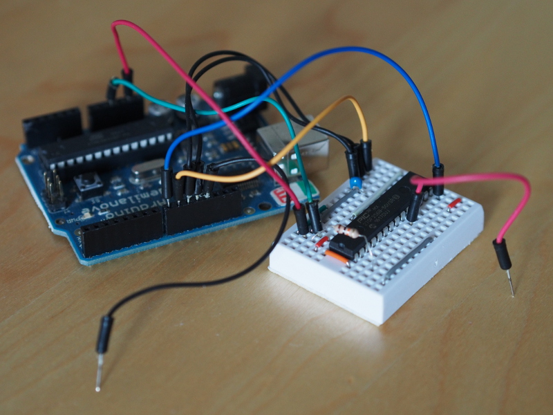
PIC32 device on a mini-breadboard connected to an Arduino Duemilanove for power and programming
Programming the Device
Despite the apparent suitability of a program called pic32prog, recommended by the “cheap DIY programmer” guide, I initially found success elsewhere. I suppose it didn’t help that the circuit diagram was rather hard to follow for me, as someone who isn’t really familiar with certain electrical constructs that have been mixed in, arguably without enough explanation.
Initial Recommendation: ArduPIC32
Instead, I looked for a solution that used an Arduino product (not something procured from ephemeral Chinese “auction site” vendors) and found ArduPIC32 living a quiet retirement in the Google Code Archive. Bypassing tricky voltage level conversion and connecting an Arduino Duemilanove with the PIC32 device on its 5V-tolerant JTAG-capable pins, ArduPIC32 mostly seemed to work, although I did alter it slightly to work the way I wanted to and to alleviate the usual oddness with Arduino serial-over-USB connections.
However, I didn’t continue to use ArduPIC. One reason is that programming using the JTAG interface is slow, but a much more significant reason is that the use of JTAG means that the pins on the PIC32 associated with JTAG cannot be used for other things. This is either something that “everybody” knows or just something that Microchip doesn’t feel is important enough to mention in convenient places in the product documentation. More on this topic below!
Final Recommendation: Pickle (and Nanu Nanu)
So, I did try and use pic32prog and the suggested circuit, but had no success. Then, searching around, I happened to find some very useful resources indeed: Pickle is a GPL-licensed tool for uploading data to different PIC devices including PIC32 devices; Nanu Nanu is a GPL-licensed program that runs on AVR devices and programs PIC32 devices using the ICSP interface. Compiling the latter for the Arduino and uploading it in the usual way (actually done by the Makefile), it can then run on the Arduino and be controlled by the Pickle tool.
Admittedly, I did have some problems with the programming circuit, most likely self-inflicted, but the developer of these tools was very responsive and, as I know myself from being in his position in other situations, provided the necessary encouragement that was perhaps most sorely lacking to get the PIC32 device talking. I used the “sink” or “open drain” circuit so that the Arduino would be driving the PIC32 device using a suitable voltage and not the Arduino’s native 5V. Conveniently, this is the default configuration for Nanu Nanu.
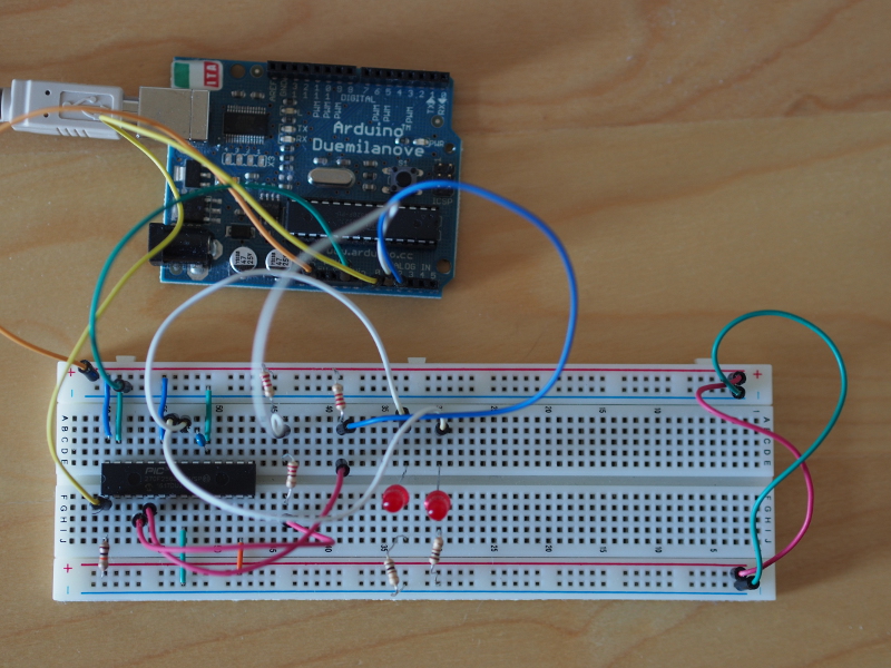
PIC32 on breadboard with Arduino programming circuit (and some LEDs for diagnostic purposes)
I should point out that the Pinguino initiative promotes USB programming similar to that employed by the Arduino series of boards. Even though that should make programming very easy, it is still necessary to program the USB bootloader on the PIC32 device using another method in the first place. And for my experiments involving an integrated circuit on a breadboard, setting up a USB-based programming circuit is a distraction that would have complicated the familiarisation process and would have mostly duplicated the functionality that the Arduino can already provide, even though this two-stage programming circuit may seem a little contrived.
Compiling Code for the Device
This is perhaps the easiest problem to solve, strongly motivating my choice of PIC32 in the first place…
Recommendation: GNU Toolchain
PIC32 uses the MIPS32 instruction set. Since MIPS has been around for a very long time, and since the architecture was prominent in workstations, servers and even games consoles in the late 1980s and 1990s, remaining in widespread use in more constrained products such as routers as this century has progressed, the GNU toolchain (GCC, binutils) has had a long time to comfortably support MIPS. Although the computer you are using is not particularly likely to be MIPS-based, cross-compiling versions of these tools can be built to run on, say, x86 or x86-64 while generating MIPS32 executable programs.
And fortunately, Debian GNU/Linux provides the mipsel-linux-gnu variant of the toolchain packages (at least in the unstable version of Debian) that makes the task of building software simply a matter of changing the definitions for the compiler, linker and other tools in one’s Makefile to use these variants instead of the unprefixed “host” gcc, ld, and so on. You can therefore keep using the high-quality Free Software tools you already know. The binutils-mipsel-linux-gnu package provides an assembler, if you just want to practise your MIPS assembly language, as well as a linker and tools for creating binaries. Meanwhile, the gcc-mipsel-linux-gnu package provides a C compiler.
Perhaps the only drawback of using the GNU tools is that people using the proprietary tools supplied by Microchip and partners will post example code that uses special notation interpreted in a certain way by those products. Fortunately, with some awareness that this is going on, we can still support the necessary functionality in our own way, as described below.
Configuring the Device
With the PIC32, and presumably with the other PIC products, there is a distinct activity of configuring the device when programming it with program code and data. This isn’t so obvious until one reads the datasheets, tries to find a way of changing some behaviour of the device, and then stumbles across the DEVCFG registers. These registers cannot be set in a running program: instead, they are “programmed” before the code is run.
You might wonder what the distinction is between “programming” the device to take the code you have written and “programming” the configuration registers, and there isn’t much difference conceptually. All that matters is that you have your program written into one part of the device’s memory and you also ask for certain data values to be written to the configuration registers. How this is done in the Microchip universe is with something like this:
#pragma config SOMETHING = SOMEVALUE;
With a basic GNU tool configuration, we need to find the equivalent operation and express it in a different way (at least as far as I know, unless someone has implemented an option to support this kind of notation in the GNU tools). The mechanism for achieving this is related to the linker script and is described in a section of this article presented below. For now, we will concentrate on what configuration settings we need to change.
Recommendation: Disable JTAG
As briefly mentioned above, one thing that “everybody” knows, at least if they are using Microchip’s own tools and are busy copying code from Microchip’s examples, is that the JTAG functionality takes over various pins and won’t let you use them, even if you switch on a “peripheral” in the microcontroller that needs to use those pins. Maybe I am naive about how intrusive JTAG should or should not be, but the lesson from this matter is just to configure the device to not have JTAG features enabled and to use the ICSP programming method recommended above instead.
Recommendation: Disable Watchdog Timer
Again, although I am aware of the general concept of a watchdog timer – something that resets a device if it thinks that the device has hung, crashed, or experienced something particularly bad – I did not expect something like this to necessarily be configured by default. In case it is, and one does see lots of code assuming so, then it should be disabled as well. Otherwise, I can imagine that you might experience spontaneous resets for no obvious reason.
Recommendation: Configure the Oscillator and Clocks
If you need to change the oscillator frequency or the origin of the oscillator used by the PIC32, it is perhaps best to do this in the configuration registers rather than try and mess around with this while the device is running. Indeed, some configuration is probably unavoidable even if there is a need to, say, switch between oscillators at run-time. Meanwhile, the relationship between the system clock (used by the processor to execute instructions) and the peripheral clock (used to interact with other devices and to run things like timers) is defined in the configuration registers.
Linker Scripts
So, to undertake the matter of configuration, a way is needed to express the setting of configuration register values in a general way. For this, we need to take a closer look at linker scripts. If you routinely compile and link software, you will be using linker scripts without realising it, because such scripts are telling the tools things about where parts of the program should be stored, what kinds of addresses they should be using, and so on. Here, we need to take more of an interest in such matters.
Recommendation: Expand a Simple Script
Writing linker scripts does not seem like much fun. The syntax is awkward to read and to produce as a human being, and knowledge about tool output is assumed. However, it is possible to start with a simple script that works for someone else in a similar situation and to modify it conservatively in order to achieve what you need. I started out with one that just defined the memory regions and a few sections. To avoid reproducing all the details here, I will just show what the memory regions for a configuration register look like:
  config2                    : ORIGIN = 0xBFC00BF4, LENGTH = 0x4
  physical_config2           : ORIGIN = 0x3FC00BF4, LENGTH = 0x4
This will be written in the MEMORY construct in the script. What they tell us is that config2 is a region of four bytes starting at virtual address 0xBFC00BF4, which is the location of the DEVCFG2 register as specified in the PIC32MX270 documentation. However, this register actually has a physical address of 0x3FC00BF4. The difference between virtual addresses and physical addresses is perhaps easiest to summarise by saying that CPU instructions would use the virtual address when referencing the register, whereas the actual memory of the device employs the physical address to refer to this four-byte region.
Meanwhile, in the SECTIONS construct, there needs to be something like this:
  .devcfg2 : {
        *(.devcfg2)
        } > config2 AT > physical_config2
Now you might understand my remark about the syntax! Nevertheless, what these things do is to tell the tools to put things from a section called .devcfg2 in the physical_config2 memory region and, if there were to be any address references in the data (which there isn’t in this case), then they would use the addresses in the config2 region.
Recommendation: Define Configuration Sections and Values in the Code
Since I have been using assembly language, here is what I do in my actual program source file. Having looked at the documentation and figured out which configuration register I need to change, I introduce a section in the code that defines the register value. For DEVCFG2, it looks like this:
.section .devcfg2, "a"
.word 0xfff9fffb        /* DEVCFG2<18:16> = FPLLODIV<2:0> = 001;
                        DEVCFG2<6:4> = FPLLMUL<2:0> = 111;
                        DEVCFG2<2:0> = FPLLIDIV<2:0> = 011 */
Here, I fully acknowledge that this might not be the most optimal approach, but when you’re learning about all these things at once, you make progress as best you can. In any case, what this does is to tell the assembler to include the .devcfg2 section and to populate it with the specified “word”, which is four bytes on the 32-bit PIC32 platform. This word contains the value of the register which has been expressed in hexadecimal with the most significant digit first.
Returning to our checklist of configuration tasks, what we now need to do is to formulate each one in terms of configuration register values, introduce the necessary sections and values, and adjust the values to contain the appropriate bit patterns. The above example shows how the DEVCFG2 bits are adjusted and set in the value of the register. Here is a short amplification of the operation:
| DEVCFG2 Bits | |||||||
|---|---|---|---|---|---|---|---|
| 31…28 | 27…24 | 23…20 | 19…16 | 15…12 | 11…8 | 7…4 | 3…0 |
| 1111 | 1111 | 1111 | 1001 FPLLODIV<2:0> |
1111 | 1111 | 1111 FPLLMUL<2:0> |
1011 FPLLIDIV<2:0> |
| f | f | f | 9 | f | f | f | b |
Here, the underlined bits are those of interest and have been changed to the desired values. It turns out that we can set the other bits as 1 for the functionality we want (or don’t want) in this case.
By the way, the JTAG functionality is disabled in the DEVCFG0 register (JTAGEN, bit 2, on this device). The watchdog timer is disabled in DEVCFG1 (FWDTEN, bit 23, on this device).
Recommendation: Define Regions for Exceptions and Interrupts
The MIPS architecture has the processor jump to certain memory locations when bad things happen (exceptions) or when other things happen (interrupts). We will cover the details of this below, but while we are setting up the places in memory where things will reside, we might as well define where the code to handle exceptions and interrupts will be living:
.flash : { *(.flash*) } > kseg0_program_mem AT > physical_program_mem
This will be written in the SECTIONS construct. It relies on a memory region being defined, which would appear in the MEMORY construct as follows:
  kseg0_program_mem    (rx)  : ORIGIN = 0x9D000000, LENGTH = 0x40000
  physical_program_mem (rx)  : ORIGIN = 0x1D000000, LENGTH = 0x40000
These definitions allow the .flash section to be placed at 0x9D00000 but actually be written to memory at 0x1D00000.
Initialising the Device
On the various systems I have used in the past, even when working in assembly language I never had to deal with the earliest stages of the CPU’s activity. However, on the MIPS systems I have used in more recent times, I have been confronted with the matter of installing code to handle system initialisation, and this does require some knowledge of what MIPS processors would like to do when something goes wrong or if some interrupt arrives and needs to be processed.
The convention with the PIC32 seems to be that programs are installed within the MIPS KSEG0 region (one of the four principal regions) of memory, specifically at address 0x9FC00000, and so in the linker script we have MEMORY definitions like this:
  kseg0_boot_mem       (rx)  : ORIGIN = 0x9FC00000, LENGTH = 0xBF0
  physical_boot_mem    (rx)  : ORIGIN = 0x1FC00000, LENGTH = 0xBF0
As you can see, this region is far shorter than the 512MB of the KSEG0 region in its entirety. Indeed, 0xBF0 is only 3056 bytes! So, we need to put more substantial amounts of code elsewhere, some of which will be tasked with handling things when they go wrong.
Recommendation: Define Exception and Interrupt Handlers
As we have seen, the matter of defining routines to handle errors and interrupt conditions falls on the unlucky Free Software developer in this case. When something goes wrong, like the CPU not liking an instruction it has just seen, it will jump to a predefined location and try and execute code to recover. By default, with the PIC32, this location will be at address 0x80000000 which is the start of RAM, but if the RAM has not been configured then the CPU will not achieve very much trying to load instructions from that address.
Now, it can be tempting to set the “exception base”, as it is known, to be the place where our “boot” code is installed (at 0x9FC00000). So if something bad does happen, our code will start running again “from the top”, a bit like what used to happen if you ever wrote BASIC code that said…
10 ON ERROR GOTO 10
Clearly, this isn’t particularly desirable because it can mask problems. Indeed, I found that because I had not observed a step in the little dance required to change interrupt locations, my program would be happily restarting itself over and over again upon receiving interrupts. This is where the work done in the linker script starts to pay off: we can move the exception handler, this being the code residing at the exception base, to another region of memory and tell the CPU to jump to that address instead. We should therefore never have unscheduled restarts occurring once this is done.
Again, I have been working in assembly language, so I position my exception handling code using a directive like this:
.section .flash, "a"

exception_handler:
    /* Exception handling code goes here. */
Note that .flash is what we mentioned in the linker script. After this directive, the exception handler is defined so that the CPU has something to jump to. But exceptions are just one kind of condition that may occur, and we also need to handle interrupts. Although we might be able to handle both things together, you can instead position an interrupt handler after the exception handler at a well-defined offset, and the CPU can be told to use that when it receives an interrupt. Here is what I do:
.org 0x200

interrupt_handler:
    /* Interrupt handling code goes here. *
The .org directive tells the assembler that the interrupt handler will reside at an offset of 0x200 from the start of the .flash section. This number isn’t something I have made up: it is defined by the MIPS architecture and will be observed by the CPU when suitably configured.
So that leaves the configuration. Although one sees a lot of advocacy for the “multi-vector” interrupt handling support of the PIC32, possibly because the Microchip example code seems to use it, I wanted to stick with the more widely available “single-vector” support which is what I have effectively described above: you have one place the CPU jumps to and it is then left to the code to identify the interrupt condition – what it is that happened, exactly – and then handle the condition appropriately. (Multi-vector handling has the CPU identify the kind of condition and then choose a condition-specific location to jump to all by itself.)
The following steps are required for this to work properly:
- Make sure that the CP0 (co-processor 0) STATUS register has the BEV bit set. Otherwise things will fail seemingly inexplicably.
- Set the CP0 EBASE (exception base) register to use the exception handler address. This changes the target of the jump that occurs when an exception or interrupt occurs.
- Set the CP0 INTCTL (interrupt control) register to use a non-zero vector spacing, even though this setting probably has no relevance to the single-vector mode.
- Make sure that the CP0 CAUSE (exception cause) register has the IV bit set. This tells the CPU that the interrupt handler is at that magic 0x200 offset from the exception handler, meaning that interrupts should be dispatched there instead of to the exception handler.
- Now make sure that the CP0 STATUS register has the BEV bit cleared, so that the CPU will now use the new handlers.
To enable exceptions and interrupts, the IE bit in the CP0 STATUS register must be set, but there are also other things that must be done for them to actually be delivered.
Recommendation: Handle the Initial Error Condition
As I found out with the Ben NanoNote, a MIPS device will happily run in its initial state, but it turns out that this state is some kind of “error” state that prevents exceptions and interrupts from being delivered, even though interrupts may have been enabled. This does make some kind of sense: if a program is in the process of setting up interrupt handlers, it doesn’t really want an interrupt to occur before that work is done.
So, the MIPS architecture defines some flags in the CP0 STATUS register to override normal behaviour as some kind of “fail-safe” controls. The ERL (error level) bit is set when the CPU starts up, preventing errors (or probably most errors, at least) as well as interrupts from interrupting the execution of the installed code. The EXL (exception level) bit may also be set, preventing exceptions and interrupts from occurring even when ERL is clear. Thus, both of these bits must be cleared for interrupts to be enabled and delivered, and what happens next rather depends on how successful we were in setting up those handlers!
Recommendation: Set up the Global Offset Table
Something that I first noticed when looking at code for the Ben NanoNote was the initialisation of a register to refer to something called the global offset table (or GOT). For anyone already familiar with MIPS assembly language or the way code is compiled for the architecture, programs follow a convention where they refer to objects via a table containing the addresses of those objects. For example:
| Offset from Start | Member |
|---|---|
| +0 | 0 |
| +4 | address of _start |
| +8 | address of my_routine |
| +12 | address of other_routine |
| … | … |
But in order to refer to the table, something has to have the address of the table. This is where the $gp register comes in: it holds that address and lets the code access members of the table relative to the address.
What seems to work for setting up the $gp register is this:
        lui $gp, %hi(_GLOBAL_OFFSET_TABLE_)
        ori $gp, $gp, %lo(_GLOBAL_OFFSET_TABLE_)
Here, the upper 16 bits of the $gp register are set with the “high” 16 bits of the value assigned to the special _GLOBAL_OFFSET_TABLE_ symbol, which provides the address of the special .got section defined in the linker script. This value is then combined using a logical “or” operation with the “low” 16 bits of the symbol’s value.
(I’m sure that anyone reading this far will already know that MIPS instructions are fixed length and are the same length as the address being loaded here, so it isn’t possible to fit the address into the load instruction. So each half of the address has to be loaded separately by different instructions. If you look at the assembled output of an assembly language program employing the “li” instruction, you will see that the assembler breaks this instruction down into “lui” and “ori” if it needs to. Note well that you cannot rely on the “la” instruction to load the special symbol into $gp precisely because it relies on $gp having already been set up.)
Rounding Off
I could probably go on about MIPS initialisation rituals, setting up a stack for function calls, and so on, but that isn’t really what this article is about. My intention here is to leave enough clues and reminders for other people in a similar position and perhaps even my future self.
Even though I have some familiarity with the MIPS architecture, I suppose you might be wondering why I am not evaluating more open hardware platforms. I admit that it is partly laziness: I could get into doing FPGA-related stuff and deploy open microcontroller cores, maybe even combining them with different peripheral circuits, but that would be a longer project with a lot of familiarisation involved, plus I would have to choose carefully to get a product supported by Free Software. It is also cheapness: I could have ordered a HiFive1 board and started experimenting with the RISC-V architecture, but that board seems expensive for what it offers, at least once you disregard the pioneering aspects of the product and focus on the applications of interest.
So, for now, I intend to move slowly forwards and gain experiences with an existing platform. In my next article on this topic, I hope to present some of the things I have managed to achieve with the PIC32 and a selection of different components and technologies.