Paul Boddie's Free Software-related blog
Paul's activities and perspectives around Free Software
Experiments with a Screen
Not much to report, really. Plenty of ongoing effort to overhaul my L4Re-based software support for the MIPS-based Ingenic SoC products, plus the slow resumption of some kind of focus on my more general framework to provide a demand-paged system on top of L4Re. And then various distractions and obligations on top of that.
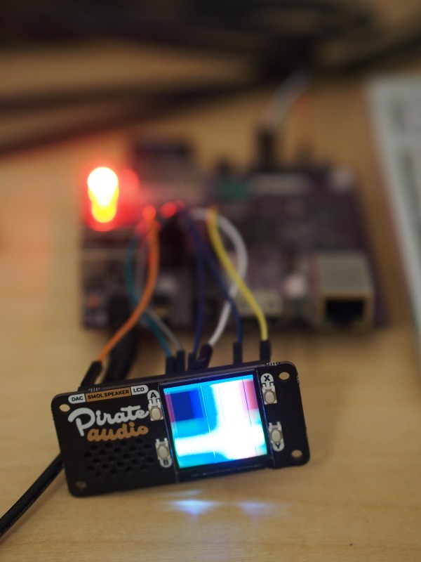
Anyway, here is a picture of some kind of result:

The MIPS Creator CI20 driving the Pirate Audio Mini Speaker board’s screen.
It shows the MIPS Creator CI20 using a Raspberry Pi “hat”, driving the screen using the SPI peripheral built into the CI20’s JZ4780 SoC. Although the original Raspberry Pi had a 26-pin expansion header that the CI20 adopted for compatibility, the Pi range then adopted a 40-pin header instead. Hopefully, there weren’t too many unhappy vendors of accessories as a result of this change.
What it means for the CI20 is that its primary expansion header cannot satisfy the requirements of the expansion connector provided by this “hat” or board in its entirety. Instead, 14 pins of the board’s connector are left unconnected, with the board hanging over the side of the CI20 if mounted directly. Another issue is that the pinout of the board employs a pin as a data/command pin instead of as its designated function as a SPI data input pin. Whether the Raspberry Pi can configure itself to utilise this pin efficiently in this way might help to explain the configuration, but it isn’t compatible with the way such pins are assigned on the CI20.
Fortunately, the CI20’s designers exposed a SPI peripheral via a secondary header, including a dedicated data/command pin, meaning that a few jumper wires can connect the relevant pins to the appropriate connector pins. After some tedious device driver implementation and accompanying frustration, the screen could be persuaded to show an image. With the SPI peripheral being used instead of “bit banging”, or driving the data transfer to the screen controller directly in software, it became possible to use DMA to have the screen image repeatedly sent. And with that, the screen can be used to continuously reflect the contents of a generic framebuffer, becoming like a tiny monitor.
The board also has a speaker that can be driven using I2S communication. The CI20 doesn’t expose I2S signals via the header pins, instead routing I2S audio via the HDMI connector, analogue audio via the headphone socket, and PCM audio via the Wi-Fi/Bluetooth chip, presumably supporting Bluetooth audio. Fortunately, I have another means of testing the speaker, so I didn’t waste half of my money buying this board!